EasyManua.ls Logo

Drinkwell 360 - Pump and Cone Assembly; Filter Installation; Filter Preparation Note

Drinkwell 360
12 pages
Print Icon
To Next Page IconTo Next Page
To Previous Page IconTo Previous Page
Loading...
www.petfountain.com
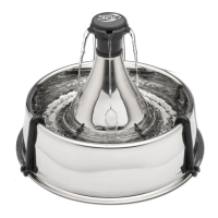
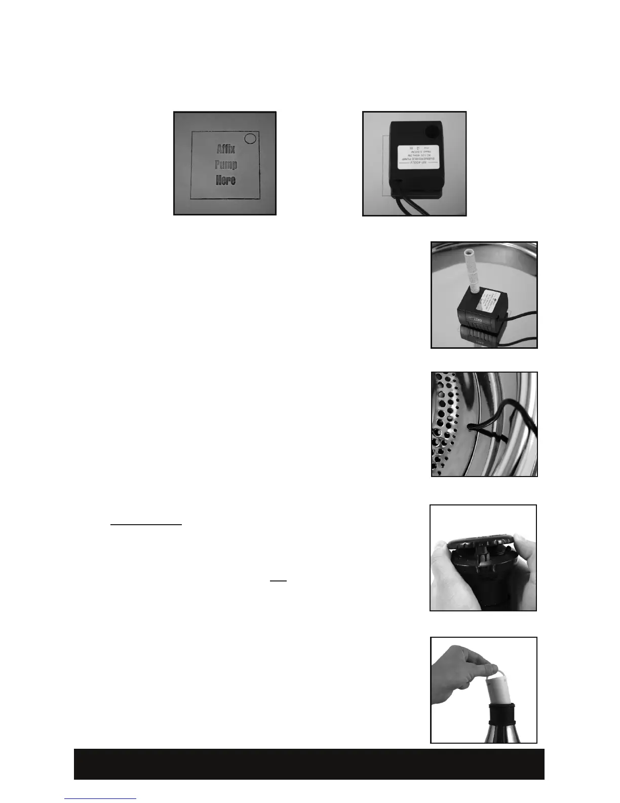
3) Place the pump in the bowl. Align the pump so that the circular opening on
the top of the motor is directly above the circle outlined on the bowl. The
pump should be aligned with the top right corner of the box outlines on the

Figures 3a-b)
IMPORTANT: Rinse the lter thoroughly under cool
water before placing into the housing! This will remove
any loose charcoal dust, which is harmless to your pet.
A small amount of charcoal dust may shed for the life
not harmful to your pet.

performance. Filters may need to be changed more
frequently depending on the number of pets using the




Consult the Fountain Disassembly and Cleaning Section
of this manual for details on cleaning and maintaining your
fountain.
Fig. 7
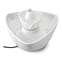
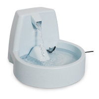
4) Place the intake tube into the circular opening on the


align the cone so that the cord runs through the cord

place the cone piece into resting position.

remove the Flow Control Cap by gently lifting straight

Gently lift up and remove the Spout Ring to access
the Filter Housing Cap.
 


screw on the Filter Housing Cap.
Fig. 3b
Fig. 4
Fig. 5
Fig. 6
Fig. 7
Fig. 3a
pg. 2

Related product manuals