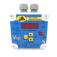
ADVANCED LUBRICATION CONTROLLER
with Quick Remote Configuration
INSTRUCTION AND PRODUCT DATA SHEET
1. DESCRIPTION:
This high performance/low cost Advanced Lubrication
Controller has been designed to control and monitor most
small to medium size lubrication systems.
The configuration parameters are all electronically stored,
in two separate menus, eliminating the need to set DIP
switches or jumpers,
The Operator Menu - is used to adjust pause and cycle
intervals.
The Factory/System Menu - is used to configure the type
of pump and lubrication system to which the controller is
connected.
In addition the controller incorporates a scanner located
under the remote control symbol on the front panel. When
used with the Transmitter Module, the configuration can
be downloaded and stored simply by positioning the mod-
ule over the symbol and pressing the transmit button
This allows for a considerable time saving for OEM’s. who
use the system on a production line, eliminating the need
to individually configure each controller.
2. SPECIFICATION:
INPUT CONTACTS:
Power:
110V/230V, 24V, 220V Single Phase
and 380V Three Phase
Power Consumption:
20 Watts.
Operating Temperature:
-5
o
C. to +55
o
C.
Control Input:
12V Max.
N.O. Pressure Switch.
Micro/Reed Switch.
Proximity (NPN/PNP Autodetection.
Oil Level:
12V Max.
Make on Low Level.
Impulse Counter:
Max. Switching Frequency;
10Hz. at 25%
OUTPUTS:
Pump/Drive Line:
110V/230V 5A 50/60Hz. or 24V
Alarm Output:
Voltage Free Contact. Max. 250V, 1A.
ENCLOSURE:
External Dimensions:
132 x 132 x 60 mm.
Fixing Dimensions:
95 x 95 mm.
Protection Grade:
IP55.
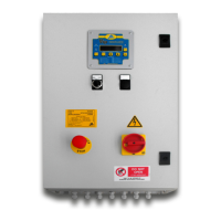
3. INSTALLATION/OPERATION:
MENU OPERATION: (Refer to table on page 2.)
ELECTRICAL CONNECTIONS AND
CIRCUIT DETAILS:
(Refer to Fig. 1.)
Note: When using the pause timer it is possible to
suspend the timer by closing contacts 14 and 15.
DIMENSIONS:
(Refer to Fig. 2.)
4. TEST PROCEDURES:
The Controller will self-diagnose on power-on and will
display any errors on the 4-digit display.
1639076
1639077
PATENT PENDING
1
C1019IE-10/97