Do you have a question about the DROPSA VIP5 Pro and is the answer not in the manual?
Defines the Lubrication Phase and Lubrication Cycle, including their components and the Standby Phase.
Explains the operating principles for CYCLE and PULSE modes, detailing distinct phases.
Describes the pre-lubrication phase and its conditions for activation.
Details the Lubrication Phase, including cycle components like Control, Delay, and Wait periods.
Explains the Standby Phase, where the system is inactive and waits for the next lubrication.
Describes the VIP5 Pro's function as a flow monitoring device.
Details the available connection terminal strips and general wiring precautions.
Provides important notes and precautions for electrical connections and wiring.
Lists crucial safety precautions for working inside the panel and making connections.
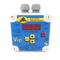
Describes the layout of the front panel and the function of its LEDs and buttons.
Explains the operation of the VIP5 Pro in CYCLE mode, with various standby determination examples.
Details the PULSE mode operation, where phases are determined by external counters.
Describes the VIP5 Pro's functionality in FLOW mode as a monitoring device.
Explains the Prelube cycle, a pre-lubrication phase triggered on power-up or reset.
Covers Dual Line, Timer, Pressure Switch, and Series Progressive monitoring methods.
Guide to accessing and using the setup menu.
Detailed list of configurable parameters and their settings.
Describes additional user-configurable functions.
Provides a list of common alarm codes and troubleshooting steps.
Explains how to reset the system after an alarm.
Describes how the controller signals alarms remotely.
Provides instructions for unpacking the equipment and checking for transport damage.
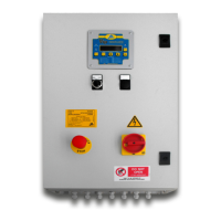
Offers recommendations for physically mounting and wiring the VIP5 Pro controller.
| Brand | DROPSA |
|---|---|
| Model | VIP5 Pro |
| Category | Controller |
| Language | English |