22/27
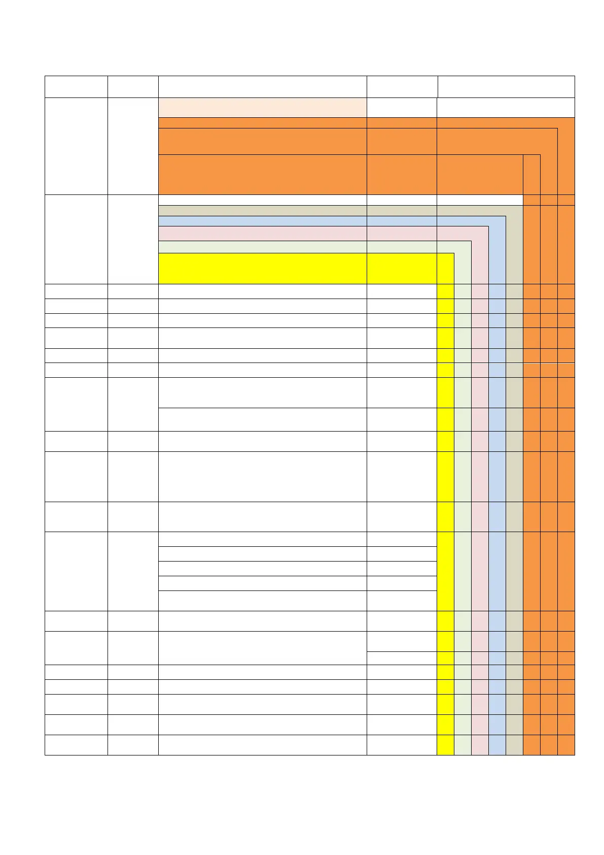
9.2 PARAMETERS AND VALUES
The following table shows the parameters and possible values of VIP5 Pro. The first two parameters (MODE and
TYPE) determine what parameters are available in the menu and they are the first that must be set.
SELECT THE OPERATIMG MODE:
Lubrication Cycle completed when the cycle sensor
confirms correct lubrication
Both Standby and Lubrication Phase determined by
external signal.
SELECTS THE CYCLE MONITORING:
Dual Line cycle with control signals
Type of connected inverter for Dual systems
Waiting time for inversion command and pump
Timeout counter determines how long to wait for cycle
completion before a timeout alarm is generated
In timer Mode, how long the pump will run
The Duration of the Lubrication cycle (in PULSE Mode)
When the pressure switch is made, how long to keep the
pump running to ensure that the signal is genuine and not a
pressure spike
With FLOW mode time that alarm condition must exist
before being reported
In Pulse Mode, will suspend the Lubrication Phase if a signal
is not received
Counter for standby phase (PULSE input).
See: PAUSE MULTIP.
Null -250
(cycle mode)
Null-60000
(pulse mode)
With cycle mode suspend remote signal on pulse input can
be connected. The lubrication cycle is completed before
any suspension
Never, In Pause
In Cycle, Always
Determines Standby Phase Timing
A set number of external PULSE signals
Whichever of above 2 events occurs first
By PULSE signals. However, if PAUSE TIM. is reached, an
alarm will be given
Standby Timer setting. Null means the standby phase will
be skipped
Pump output can be constant signal, pulsed signal or
synchronized with control signal (see next 3 parameters)
Sets the ON value of the pump pulse
Sets the OFF value of the pump pulse
Multiply pause settings by 10 or 100 to achive more higt
values. See: PAUSE CNT
Number of Lubrication Cycles to complete a Lubrication
Phase
In a SEP mode, If P2 input is closed the LUBE CYCLES values
is increased by this value contained in this setting