25/27
10.3 REMOTE CODED ALARM FUNCTION
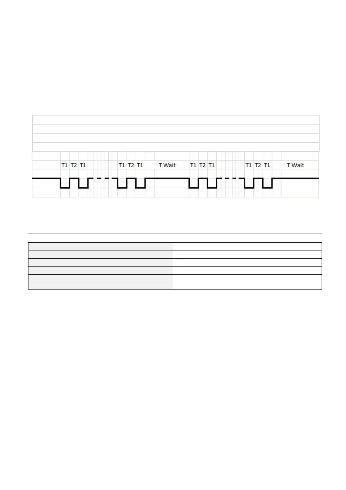
The VIP5 controller has the ability to use a remote pulsed coded alarm contact.
Every time the VIP5 control enters an alarm condition, the remote alarm relay contact is activated.
Most alarm contacts are simply a NC or NO contact that gives a remote system indication that the local controller is in a
fault condition.
Additionally, the VIP5 can trigger the alarm according to the alarm code being generated and allow a remote PLC (or even a
remote LAMP signal) to read the number of the alarm being generated.
This is done by pulsing the alarm relay in 500ms bursts with a 2000ms gap between each signal burst.
The timing chart below shows how to interface the logic with your PLC.
11. TECHNICAL SPECIFICATIONS
Supply voltage (see note par.5.1)
110V~ - 230V~ - 400V~ - 460V~
2 W (In Stop) - 10 W (In Start)
Temperature Operating Range
Permissible Temperature storage range
Operating Relative Humidity
Alarm code= number of (T1+T2)
T1= 500ms = alarm contact activation time
T2= 500ms = alarm contact deactivation time
TWait= 2000ms= pause time before repetition of same alarm code