10/27
5. INPUTS/OUTPUTS
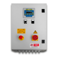
5.1 ELECTRICAL CONNECTIONS
As indicated on the electrical diagram of equipment (Part #1327290), it is suggested to use 2.5 mm2 section cable. The
maximum thermal protection mounted on equipment can be 4 A.
These connections are routed from the main terminal boards on the 1639186 board according tables below. For
correct wiring you should note the following:
1. All input and output signals refer to a nominal voltage of 24Vdc.
2. The outputs on terminal board M1 refer to voltage indicated as Vio on terminal 6 and 7 of M2.
3. The framework is provided with (Vio) power supply input coinciding with (Vint) internal power supply via
bridges on the terminals: M2:M2.5 with M2.4 with M2.6.
The inputs are provided galvanic isolated.
4. If you want to enter with active signals whose 24V alimentation is taken outside the framework is
necessary to remove the connections on M2.5 with M2.7 and M2.4 with M2.6. In this case is also
necessary carry this power to M2.7 and M2.6 in according to polarity.
5. The connections for dual line commands on M5 are configured for 24Vdc changeover valve. If it the
changeover solenoid use different power supply, remove connections on terminal M7 and M5 and
connect the appropriate voltage on M5.3 and M5.4.
6. Connections on terminal M6 aren't clean contacts.
7. Connections on terminal M4 are SPDT type clean contacts.
NOTA: Nel collegamento dei dispositivi “da e verso il campo”, utilizzare le canalizzazioni predisposte
internamente al quadro.
Eseguire i collegamenti sempre con quadro privo di alimentazione.
Tutti i collegamenti devono essere eseguiti da personale qualificato e autorizzato nel rispetto delle
normative vigenti.
Accertarsi che i fili:
- Possiedano una lunghezza adeguata;
- Possiedano un grado d'isolamento adeguato e integro fino al loro ingresso nel morsetto;
- Siano correttamente bloccati.
ATTENZIONE: Il quadro standard ha un’alimentazione di rete 400V~.
Nelle varianti (A-B-C-D-E) verificare come riportata nel paragrafo 14 il valore di alimentazione
corrispondente.
La non osservanza di tale prescrizione potrebbe causare danni permanenti al quadro di controllo.