EasyManua.ls Logo

DROPSA VIP5 Pro - Page 9

DROPSA VIP5 Pro
27 pages
Print Icon
To Next Page IconTo Next Page
To Previous Page IconTo Previous Page
Loading...
9/27
Table 3
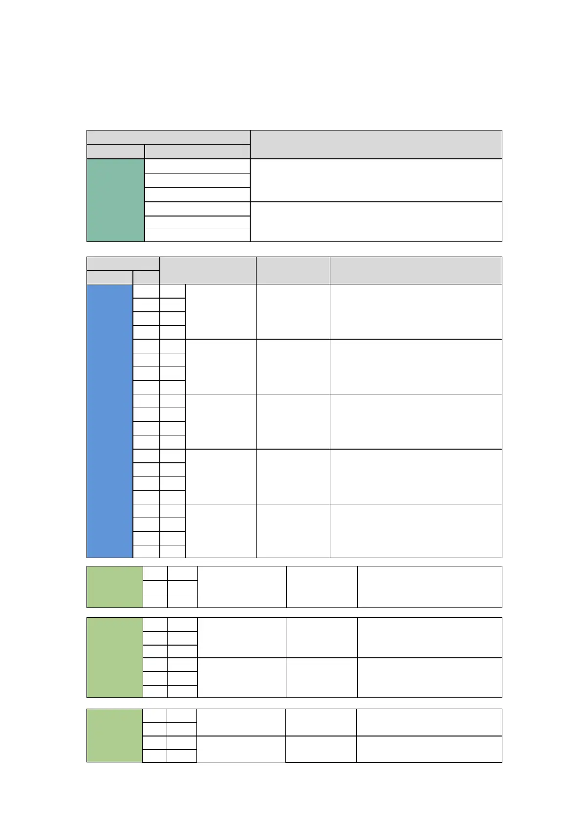
There are five connection terminal strips inside the panel called XM0, XM1, XM3, XM4 and XM5 (see image below). The
panel power supply voltage and the three-phase output command toward the pump should be connected to the XM0
terminal strip. The XM1 and XM3 terminal strips, on the other hand, should be used for the connection of panel input
devices as indicated in the table. Connect the output signals to terminal strips XM4 and 5.
Location
Function
Block
Num
XM0
1
SUPPLY PANEL
2
3
4
PUMP CONTROL
5
6
Block
Signal level
Function
Notes
Block
Num
XM1
+
+
DIGITAL INPUT
MAXIMUM
LEVEL INPUT
IF SENSOR IS EXI CERTIFIED, CONNECT TO
BARRIER, XD 1/2
(SIMPLE DEVICE)
17
PNP
-
-
18
NPN
+
+
DIGITAL INPUT
MINIMUM
LEVEL INPUT
19
PNP
-
-
20
NPN
+
+
DIGITAL INPUT
PULSE
INPUT/SUSPEND
23
PNP
-
-
24
NPN
+
+
DIGITAL INPUT
PRESSURE
SWITCH 1 INPUT
IF SENSOR IS EXI CERTIFIED, CONNECT TO
BARRIER, XD 4/5/6
(SIMPLE DEVICE)
25
PNP
-
-
26
NPN
+
+
DIGITAL INPUT
PRESSURE
SWITCH 2 INPUT
27
PNP
-
-
28
NPN
XM3
3
IN
ANALOG INPUT
LASER PROBE
4
IN
+
+
XM4
8
C
DIGITAL OUTPUT
MIN LEVEL
ALARM
9
NC
10
NO
11
C
DIGITAL OUTPUT
COMM.ALARM
12
NC
13
NO
XM5
1
OUT
SOLENOID VALVE
LINE 1
2
OUT
5
OUT
SOLENOID VALVE
LINE 2
6
OUT

Related product manuals