14/27
5.2 ACTIVATING THE BATTERY FOR REAL TIME CLOCK FUNCTIONS
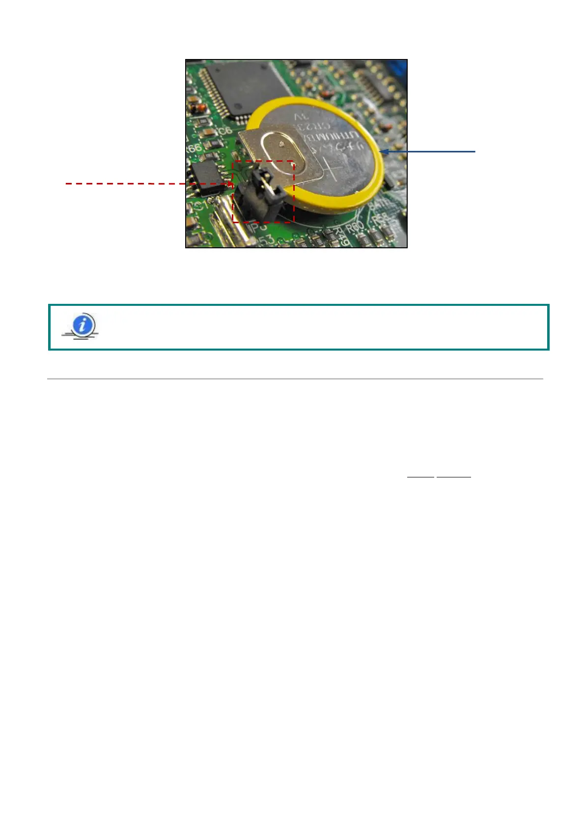
By inserting the Jumper into the bridging pins, the battery function is activated and this allows the VIP5 Pro to operate
with the Date/time and status save function when the power is removed.
5. PARTICULAR PRECAUTIONS WHILE CARRYING OUT CONNECTIONS
5.1 ELECTRICAL CONNECTIONS
Never access the inside of the panel without first activating the door lock disconnect switch (Yellow-Red), positioning it to
Opening = position 0
To safely operate inside the panel, the power supply upstream of it must be interrupted, acting on the line where
the necessary protections and necessary disconnect switches will be installed.
If you must operate on electrical devices far from the panel (downstream of it), but connected to it, it is
compulsory (in addition to activating the door lock disconnect switch) to insert a safety padlock in the appropriate
slot provided in the disconnect switch itself. This is to prevent any accidental activation of the voltage by external
personnel or distracted co-workers while you are operating on peripheral electrical controls.
Always strictly follow the diagram attached to each panel. In the event of any doubt on connections that do not
seem clear, ask our Technical Office before carrying out dangerous attempts.
Ensure that the power supply to the panel is correct based on the characteristics for which the panel was
constructed.
The power supply to the door lock disconnect switch must come from a specific dedicated line on which (upstream
of the panel) a device must be installed suitable for protection of indirect contacts (differential protection)
It will therefore be the installing technician’s duty to guarantee protection of indirect contacts, installing (or having
installed by qualified personnel) an automatic power supply interruption with specific differential or magnetic-
thermal type devices, depending on the prevailing standards (CEI 64-8). A disconnect switch upstream of the panel
is always required. Qualified personnel capable of assessing the choice must be used, taking into consideration:
the existing power supply circuit
a maximum short circuit current (Icu) of 10ka
the existing grounding system
the diagram of the panel and its application
Moreover, for the protection of indirect contacts, a grounding connection is predisposed:
a) Male bolt with ring and yellow green cable or
b) Ground terminal strip
Note: Every time the battery jumper is removed and reinserted causes the DATE/TIME function to be
set to zero. Therefore it is recommended that after inserting the battery jumper, the date and time is
set.
Set the JUMPER
(as shown) to ability
the battery