5/27
4. INLETS/OUTLETS
4.1 ELECTRICAL CONNECTIONS
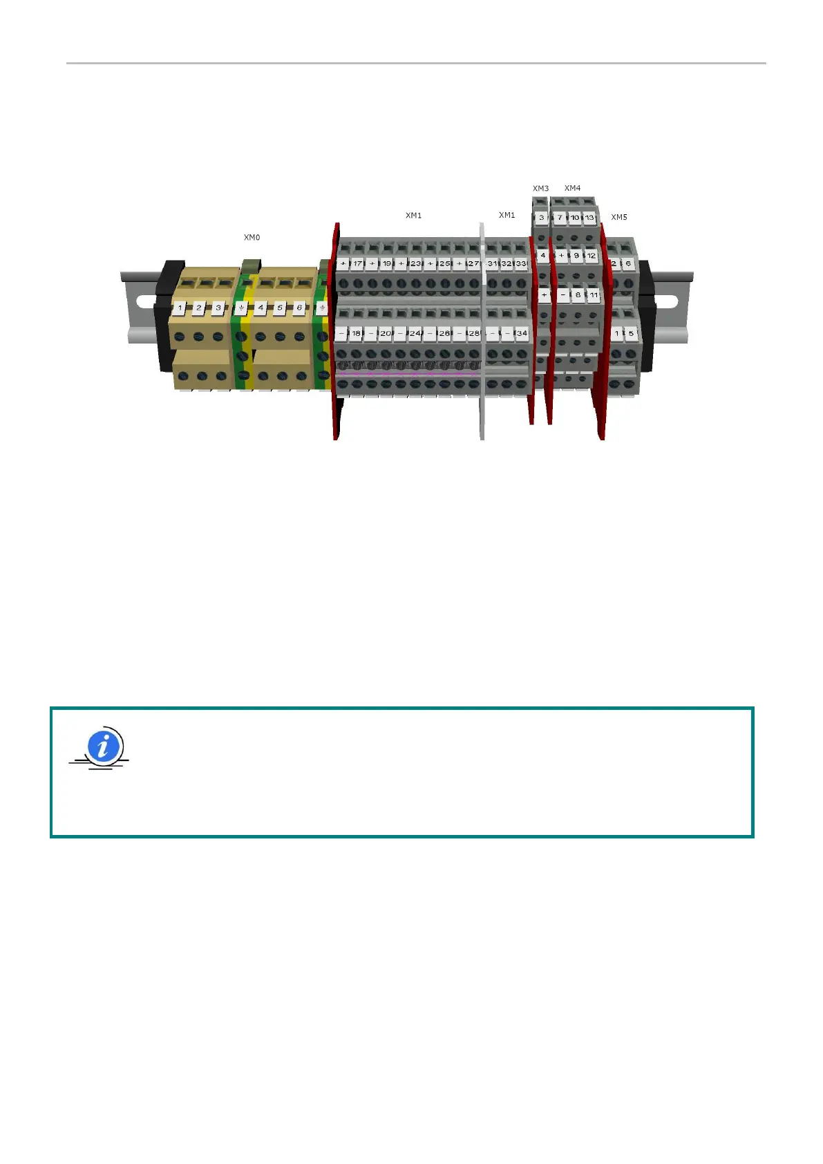
Inside the panel there are 6 connection terminal strips available (see image).
XM0 power supply connection of the panel and to the three-phase command of the outlet pump
XM1 digital inputs connection
XM3 analogue inputs connection
XM4 exchange signals connection
XM5 digital outlet connection (pneumatic or electromagnetic valve)
The connection of the cables in the terminal strip depends on the type of configuration used (SEP, DUAL, TIME, DUAL
TIME, PS).
The various associations are listed in Table 1. The XM1 terminal strip can be configured for connection of the PNP or
NPN devices, simply moving the common bar (see Tables 2 and 3, highlighted in yellow).
In the connection of the “from and to the field” devices, use the predisposed channelling entirely in the
panel; take care to ensure that the wires are not short, that they always have adequate insulation in good
condition all the way to the terminal strip, and that they are correctly tightened.
Always carry out connections with the panel disconnected from power.
All connections must be carried out by qualified and authorised personnel, in compliance with the
prevailing regulations.