2
1. INTRODUCTION
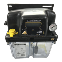
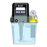
This User and Maintenance Manual refers to SMART2 - Oil Lubrication Electro-Pump.
You can find additional copies and newer revisions of this document from our website http://www.dropsa.com
.
Alternatively contact one of our Sales Offices.
This manual contains important information on health and safety issues for the personnel. It is recommended
to attentively read this manual and carefully keep it in good condition so that it is always available to personnel
requiring to consult it.
2. GENERAL DESCRIPTION
Oil lubrication pump SMART2 has been designed for industry machine tools.The electric gear-pump was
designed to work with Single Line Injectors and Valves 33.
SMART2 is available in two versions:
- Manual SMART2, manually controlled via the PLC of the machine tool;
- Automatic SMART2, automatically controlled via built-in VIP2004 controller.
2.1 LUBRICATION CONTROL SYSTEM - PRINCIPLES OF OPERATION
AUTOMATIC SMART 2 operates on the principle of intermittent lubrication which involves the following
three steps:
Prelube
Lube (lube – wait)
Standby
2.1.1 PRELUBE
This step is made up of a set of cycles (max 999 cycles) during which the lubrication system runs a series of
lubrication cycles (lubrication will be described in paragraph 2.1.2) necessary to vent air from the pump and
check lubrication functions.
Prelube takes place:
- on POWER-ON;
- on RESET;
- Any time new parameters are set.
When prelube is set to “0”, Intermittent Lubrication will only consist in the lube – standby/standby - lube
phases (see START mode).
2.1.2 LUBE
This step is made up of a set of cycles (max 999 cycles) during which lubrication is carried out. Each cycle
consists of two sub-cycles (lube and wait) and involves the monitoring of timers and/or inputs:
- during lube, system delivers lubricant to the lubrication points;
- during wait, a timer defines the wait time between two or more lube cycles or before the beginning of
the standby phase (in case only 1 lube cycle was set).
There are three types of lube:
TIMER: Lubricant delivery is simply regulated by a timer;
PS: Lubricant delivery is carried out only if the system is in pressure;
SEP: Lubricant delivery is carried out only the system detects three changes in the position of the
mechanical piston.
2.1.3 STANDBY
During this step lubrication system is idle until the next lubrication cycle. There are three ways to regulate
standby:
TIMER: a timer regulate system idling;
PULSE: a pulse counter regulate system idling;
BOTH: both a timer and a pulse counter regulate system idling. The type of standby will depend on
which of these two events will start first.