8
7. INSTRUCTIONS FOR USE
7.1 Manual SMART2
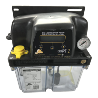
When the unit is equipped with the manual system, located on the frontal side panel you find the PUMP-ON
indicator which is on when the pump is operating. Remote control is via external timer or PLC.
Warning:
Manual control device cannot be used through a direct control but must be operated through
a deck or an electronic circuit with a max power absorption of 400mA.
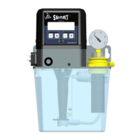
7.2 Automatic SMART2
When the unit is equipped with an automatic control, all the pump functions and checks are carried out
through the built-in VIP2004 controller, alarms and external signals included. Timers are also controlled by the
system. For details about machine operation, please refer to par. 7.4.
7.3 Machine operations
7.3.1 Prior to machine start-up
Verify the unit is undamaged.
Check that hydraulic and electric connections have been carefully carried out.
Refill the reservoir with compatible lubricant.
Verify the voltage: MAX 220VAC.
RESERVOIR REFILL
Use ONLY
compatible lubricant and refill the reservoir by means of the oil refill plug provided with a filter. Do
not pour lubricant directly into the reservoir without using this oil refill plug.
7.3.2 Machine start-up
In order to avoid damage to the machine, the unit must start operating at a minimum working temperature of
+5°C (+41°F).
Switch ON the unit.
Verify unit start-up.
Verify piping are air-bubble-free.
Adjust pressure.
Set-up machine parameters.
Verify machine correct operation: pump must carry out lubrication correctly and according
to parameters setup.
AIR VENTING
Pump well-functioning is not affected by presence of air in the system. However, it is advisable to vent air by
starting the pump until lubricant comes out air-bubbles-free. (It is recommended to avoid pump operation
when lubricant is below the minimum level).
PRESSURE REGULATION
Pressure can be verified via manometer. It is possible to regulate pressure by acting on the screw located on
the frontal side of the baseplate.
⇒ To increase pressure: turn the screw clockwise.
⇒ To decrease pressure: turn the screw anticlockwise.
In case of doubts as to correct machine functionin