EasyManua.ls Logo

DROPSA BRAVO - User Manual

Default Icon
23 pages
Print Icon
To Next Page IconTo Next Page
Loading...
Electric Lubrication pump for fixed and mobile
applications
User Operating and Maintenance Manual
Original Instructions
Manual drawn up in accordance with EC
Directive 06/42
Dropsa products can be purchased from Dropsa bracnhes and authorized distributors,
visit www.dropsa.com/contact or contact us at sales@dropsa.com
BRAVO
C2114IE WK 51/20
22/19
Question and Answer IconNeed help?

Do you have a question about the DROPSA BRAVO and is the answer not in the manual?

Summary

Introduction

General Description of Bravo Pump

Details the Bravo electric piston pump, its modular reservoir, and control options.

Centralized Lubrication Overview

Explanation of centralized lubrication systems and their benefits for machinery.

Bravo Electric Grease Pump Features

Details the Bravo electric piston pump, its modular reservoir, and control options.

Product Identification

Information on how to identify the pump, its part number, and operating voltage.

Technical Characteristics

General Technical Specifications

Table detailing operating voltage, current, weight, output, pressure, and environmental limits.

Control Panel Specifications

Details for the control panel, including voltage, load, temperature, and protection features.

Electrical Connection Specifications

Information on connector types, nominal voltage, poles, cable size, and max current.

Pump Components

Bravo Grease Pump Components

Identification of key components of the Bravo Grease pump, like reservoir and control panel.

Bravo Oil Pump Components

Identification of key components of the Bravo Oil pump, like reservoir and control panel.

Pumping Unit Identification

Electronic Control Board Modes

Describes the three operating modes for the automatic version's control board: CYCLE, PULSE, OFF.

Minimum Level Sensing

Connections and Wiring Options

Unpacking and Installing the Pump

Unpacking Instructions

Procedures for unpacking the pump and checking for transport damage.

Installing the Connector Baseplate

Steps for connecting and securing the base plate to the pump body.

Pump Installation Guidelines

Recommendations for mounting the pump, including location, clearance, and accessibility.

Installing Pump Elements

Procedure for installing or relocating pump elements, including torque specifications.

Hydraulic Connections

Installing Divider Valve

Guidance on installing an optional SMP or SMPM distributor valve to divide lubricant.

Installing IP69 K Protection Equipment

Electrical Connections and Wiring

Connector Types

Detailed diagrams showing various connector types for different voltage and version configurations.

Wiring Diagrams

Power Supply Wiring

Wiring diagrams for 12/24 VAC-VDC, 110VAC, and 230VAC power supply connections.

Cycle Sensor Wiring

Diagrams for connecting the cycle sensor in automatic and manual versions.

Minimum Level Wiring

Wiring for minimum level signaling in automatic and manual versions.

Remote Control Wiring

Diagrams for connecting remote control switches and lamps.

Remote Control Switch and Lamp Connection

Operating Instructions

Pre-Operation Checks

Essential checks and precautions to take before starting the pump.

Pump Operation

Steps for operating the pump, including mode setting and checking lubricant delivery.

Setting Adjustable Pumping Unit

Procedure to adjust the flow rate of the progressive pumping unit.

Refilling the Reservoir

Pump Configuration (Automatic Version)

Overview of the automatic version's control panel layout and button functions.

Manual Version Operation Mode

Automatic Version - CYCLE Mode

Automatic Version - PULSE Mode

Automatic Version - OFF Mode

Programming the Electrical Controller

Special Functions and Parameters

Special Functions

Functions like locking/unlocking keyboard and resetting defaults using button combinations.

Operative Parameters

Table detailing operative parameters, modes, defaults, ranges, and notes for configuration.

Troubleshooting Guide

Troubleshooting Table and Alarm Codes

Programmed and Operational Maintenance

Scheduled maintenance tasks, including checks on tubing, reservoir, and filter.

Maintenance Procedure

Disposal Guidelines

Ordering Information

Dimensions

Handling and Transportation

Operating Hazards

Lubricant Compatibility and Hazards

Information on suitable lubricants, compatibility with seals, and comparisons of NLGI/ASTM classifications.

Precautions and Not Allowed Fluids

Overview

The DropsA BRAVO is an electric lubrication pump designed for both fixed and mobile applications, providing centralized lubrication for industrial and mobile machinery. This system significantly reduces maintenance costs, minimizes machinery downtime due to poor lubrication, and extends equipment life. It also allows for frequent lubrication of hard-to-reach points.

Function Description:

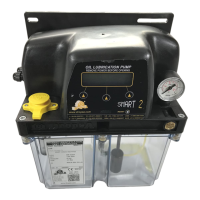
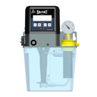
The BRAVO pump delivers oil or grease to friction points within a lubrication system. It operates as an electric piston pump, with the pumping element driven by a camshaft connected to a reducing gearbox. The pump can be fitted with up to three pumping elements, one of which is standard and may include an integrated pre-set bypass (pressure safety valve). It features a modular reservoir available in 2, 5, or 8-liter capacities, with a minimum level sensing device fitted as standard at the base. For grease versions, a stirrer device with a reservoir wiper helps eliminate air and facilitates pumping, even at lower temperatures. The pump is available in two main versions:

  1. Automatic Version: Features an integrated automatic control board that manages and monitors the pump and lubrication cycle. This version offers three operating modes:
    • CYCLE: Lube and pause cycles are set using a built-in timer or external inputs, with both conditions working in combination.
    • PULSE: Lube and pause cycles are determined by external inputs. During the lube cycle, a cycle sensor monitors system operation, and the pump can suspend lubrication if external pulses are not detected.
    • OFF: The pump operates as a slave, controlled externally by the machine.
  2. Manual Version: The pump motor is controlled externally by applying and removing power, without an integrated control board.

Important Technical Specifications:

  • Operating Voltage:
    • AC: 110V, 230V (50Hz/60Hz)
    • DC: 12V, 24V
  • Current (Nominal/Peak): Varies by voltage, e.g., 1A/6.5A for 12VDC, 0.2A/0.3A for 110VAC.
  • Nett Weight: 5.5 kg (12.12 lb) for 2-liter, 6 kg (13.22 lb) for 5-liter, 6.5 kg (14.33 lb) for 8-liter (grease version). Oil versions are slightly heavier.
  • Number of Outlets/Pumping Elements: 1 (up to 3 max).
  • Outlet Thread: 1/4" BSP.
  • Nominal Output per Pump Element (20 RPM): 2.8 cm³/min (0.17 in³/min) or 5.2 cm³/min (0.31 in³/min). Adjustable from 0.4 to 2.8 cm³/min (0.02 to 0.17 in³/min).
  • Working Pressure: 280 bar (4061 psi).
  • Integrated Bypass Pressure (if present): 320 bar ±30 bar (4641 psi ±435 psi).
  • Reservoir Capacity: 2, 5, 8 liters (0.53 – 1.32 – 2.11 gallons).
  • Max Grease Capability: NLGI 2.
  • Min. Oil Viscosity: 46 cSt.
  • Operating Temperature: -25°C to +80°C.
  • Storage Temperature: -30°C to +90°C.
  • Humidity: 90%.
  • IP Protection Grade: IP65 (IP69K with special equipment).
  • Noise: < 70 dB (A).
  • Control Panel Characteristics (Automatic Version):
    • Operating Voltage: 12VDC ±20%, 24VDC ±20%, 110VAC, 230VAC (includes internal transformer).
    • Maximum Output Load Capability: 5A.
    • Short Circuit & Overload Protection: 7.5A typical, 10A max.
    • Hardware Protection: Overload on motor and lamp, integrated motor protection, spike voltage protection, inverted polarity protection.
    • Memory: EEPROM, unlimited life (no battery requirement).
  • Minimum Level Switch: Max load 1A @ 30V (automatic), 0.3A @ 230V (automatic), 0.25A @ 120V (manual).

Usage Features:

  • Installation: The pump should be installed in an easily accessible location, allowing 100mm (4 inches) perimeter distance for maintenance and refilling. It should not be submerged in liquids or installed in hazardous areas with flammable/explosive materials, or near strong heat/electrical sources that could cause interference.
  • Pumping Element Installation: The pump is supplied with one pumping element, but additional elements can be installed in ports 2 or 3. To install, remove the plastic plug, insert, and screw the pump element until fixed, using 20Nm torque.
  • Hydraulic Connections: Connect via 1/4" BSP fittings and tubing. A 1/8" BSP port can be used as a return or remote refilling line.
  • Optional SMP or SMPM Divider Valve: Can be installed at the base of the pump to further divide lubricant.
  • IP69K Protection (Optional): Achieved by installing a specific connector plate and a keyboard protection cover, requiring removal of plugs, fitting a silicon membrane, and securing with screws.
  • Electrical Connections: Must be performed by a qualified electrician, ensuring correct operating voltage and suitable power cable. For 110V/230VAC versions, a 1A fuse T and a differential trip (30mA at 1ms max) are recommended.
  • Refilling: The reservoir is refilled through dedicated filling ports with adequate filtration to ensure clean lubricant. Overfilling will result in excess lubricant being expelled through vent holes.
  • Adjustable Pumping Unit: Flow can be adjusted from 0.4 to 2.8 cc/min (0.02 to 0.17 in³/min) over 4 rotations, with each rotation approximately 0.6 cc/min. Adjustment is made by removing an access cap and rotating an internal grub screw with a 4mm Allen wrench.
  • Control Panel (Automatic Version): Features a display, OK button (confirm/enter programming), UP/DOWN arrows (increment/decrement values), and a Reset button (resets lube cycle, cancels alarms, restarts program).
  • Remote Light Button (Optional): Constantly lit when the pump is running, flashes for minimum level or other alarms (number of flashes indicates anomaly code). Pressing during pause initiates a lubrication cycle. Holding for 6 seconds resets the pump.
  • Programming: Parameters like pause timer, pause counter, cycle timer, cycle counter, prelube, motor duty, manual input cycles, pause time overrun alarm, and minimum level can be configured via the control panel.

Maintenance Features:

  • General Maintenance: The pump requires minimal maintenance. Regular inspection and cleaning are recommended to ensure long life and trouble-free operation. All tubing should be checked for tightness and leaks.
  • Programmed Maintenance:
    • Integrity of tubing and system: Check fittings and tubing, verify components fixed to machine (after initial 500 hours, then every 1500 hours).
    • Reservoir level: Top up with clean lubricant (as needed).
    • Filling Filter: Check and replace (as needed, or once per year).
  • Troubleshooting: A comprehensive table is provided to identify possible problems (e.g., pump motor not operating, no lubricant reaching points, lubricant not reaching points regularly, no lubricant from pump, display not lit, pump starts and immediately stops) and their remedial actions. Users are advised to contact an Authorized Dropsa Sales and Service Point for technical assistance if in doubt.
  • Alarm Codes: The light button flashes to indicate specific alarms (e.g., low lubricant level, cycle sensor overrun, pause timer overrun, pump motor blocked, pump motor overload, C.COU pulses counter error, Eprom error). Alarms can be canceled by pressing the UP and DOWN arrow buttons together.
  • Lubricant Compatibility: The pump is designed for grease up to NLGI 2 or oil with a minimum 46 cSt. Only lubricants compatible with NBR (Buna) rubber seals should be used.
  • Disposal: Environmentally sensitive items like oils and lubricants must be disposed of according to local regulations. The identification label and all relative documents should also be destroyed when disposing of the unit.

DROPSA BRAVO Specifications

General IconGeneral
BrandDROPSA
ModelBRAVO
CategoryWater Pump
LanguageEnglish

Related product manuals