12
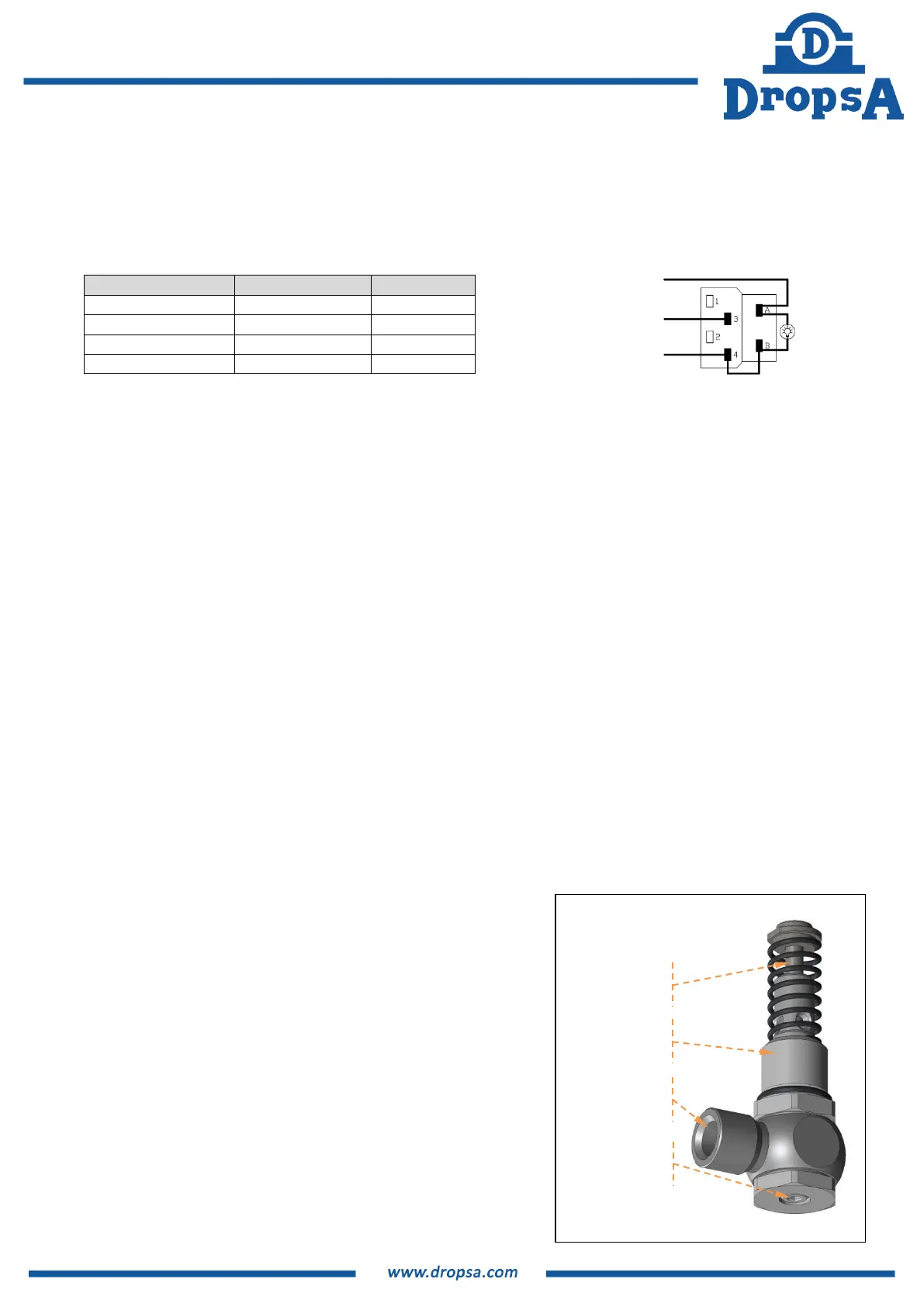
6.8.2 Remote Control switch and Lamp
After connecting the pump, it is possible to continue the installation by connecting the remote switch/lamp when in
systems where this has been installed.
Install the remote switch by the control panel of the vehicle or machine.
Refer to the following diagram to connect the switch and lamp.
7. OPERATING INSTRUCTIONS
7.1 BEFORE PUTTING INTO OPERATION
Note that the unit should not be dismantled by the user if a fault is found.
Use gloves when handling lubricants and ensure you have checked the lubricant safety data sheet.
Do not use lubricants that are incompatible with NBR (Buna) seals.
Ensure that you have complied with all health and safety requirements before putting the pump into service.
Maintain proper hygiene standards. Never ignore any potential danger to heath.
Ensure all tubing and fittings are designed to handle the maximum system pressure.
Check integrity in the pump. Ensure no damage;
Check and fill the reservoir. If the reservoir is below the MIN level, follow procedure 7.4 to refill;
Verify the pump is at the correct operating temperature and tubing is free of air bubbles;
Check the unit is properly cabled.
7.2 OPERATION
Check and set the operating mode and parameter if using the automatic versions.
Press the remote start button on your machine if using a manual version.
Check that the pump is running.
Check lubricant is being delivered to the greasing points as necessary.
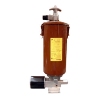
7.3 SETTING OF ADJUSTABLE PUMPING UNIT
To set the progressive pumping unit with adjustable flow, proceed as
follows:
Ensure there is no residual pressure in the pressure line.
Remove the adjustment access cap using a 4mm Allen wrench
Rotate the jacket of the pumping unit using a 4 mm Allen wrench
inserted in the internal grub screw.
Each complete rotation of the Allen wrench is approximately
0.6cc/min. Setting range from 0.4 to 2.8 cc/min. for a total of 4
rotations.
Check the presence and conformity of the copper gasket (replace
if necessary).
Replace the cap using a 4 mm Allen wrench.
LAMP
REMOTE CONTROLE
COMMON