7
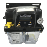
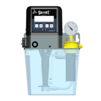
6.4.3 POWER-SUPPLY SWITCH, VARIABLE RESISTOR AND BATTERY
6.4.3.1 POWER SUPPLY SWITCH
⇒ For 220V switch rightwards.
⇒ For 110V switch leftwards.
6.4.3.2 VARIABLE RESISTOR
It allows to regulate display brightness.
6.4.3.3 BATTERY ACTIVATION
The controller is provided with a three-pin-jumper to activate battery backup of Date and Time when the
equipment is powered off.
To short-circuit the board and activate the battery, insert the bridge only into two pins (see above
picture).
WARNING:
- Each time the bridge is removed or powerfailure occurs, Date and Time are reset. It is
recommended to setup Date and Time each time the bridge is removed and then put back in
place.
- In order to make a complete reset of the machine, remove the bridge and switch-off the
machine.
6.4.4 PRECAUTIONS TO BE TAKEN DURING CONNECTING PROCEDURE
⇒ Prior to any operation, verify the voltage of the machine on the product label.
⇒ In order to prevent dangers of electric shocks due to direct or indirect contact with the
energized parts, electrical power supply line
must be protected by a suitable magneto-
thermal circuit breaker with an intervention threshold of 0.03 Ampere and 1 second
minimum operating time. Circuit breaker power must be ≤ 10 kA and nominal power In = 6
A.
BATTERY
JUMPER
At the end of all connecting operations, make sure that pipes and wires are safe from
impacts and carefully fixed.
VARIABLE
RESISTOR
POWER SUPPLY
SWITCH