Page 4 For technical questions, please call 1-888-866-5797. Item 58009
Installation Instructions
1. Construct a basin that is at least 30″ deep
and at least 18″ in diameter.
Note: Area should be cleared of small stones or gravel.
2. Secure the pump on a level, solid
base. Do not suspend the pump by the
discharge pipe, hose, or power cord.
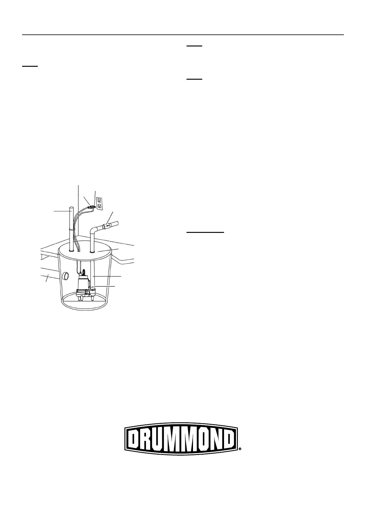
3. Position Pump on solid surface so that both hoses
are free from kinks the Float Switch is away from the
inlet pipe and at least 1″ away from all obstructions
throughout its movement. See Figure A.
4. Fit a sewage cover with a vent pipe, a hole for
the output pipe and a hole for the power cords.
Thread the Power Cords through their holes,
but do not plug them in yet. Set the
sewage cover aside for now. Place unused
end of discharge hose the other end.
1/8″ Bleed Hole
Discharge Pipe
Sewage Cover
Check Valve
(sold separately)
Float Switch Cord
Pump Cord
Inlet
Pipe
Vent
18″ Dia.
Figure A: Pump Setup
Note: The sewage cover must also
be fitted with a vent pipe.
5. Attach a discharge pipe to the Pump Outlet.
Note: Wrap all threaded connections
with PTFE thread seal tape.
6. Check Valve is sold separately. Install
according to manufacturer instructions.
7. To prevent excessive cycling from backflow of water,
install a check valve onto the discharge pipe. This
prevents water from flowing back after the pump
shuts off. Mount the check valve according to check
valve label to avoid the valve flapper getting stuck.
8. Drill a 1/8″ diameter air bleed hole through the
Discharge Pipe just above the lower Base to
prevent Pump ″airlock″. A small spray of water out
of this hole is normal while the Pump is running.
9. Connect additional Discharge Pipe as needed to
direct the discharge to the main waste line for the
sewer or septic tank. The discharge should be kept
as short as possible with a minimum number of turns.
IMPORTANT: Do not exceed the
Maximum Head Lift @ 0 Flow of the Pump.