2
INSTALLATION
AUX
12VDC
FUSE
1A
LOAD
LOAD
PGM
DEVICE
CONTROLLED
DEVICE
300 mA MAX
TO AUX+
TERMINAL
Bell Loop Wiring Chart
AWG AWG AWG AWG AWG
Current 14 16 18 19 22
mA Distance to last bell or siren (ft./m.)
100 2375/724 1500/457 940/287 750/229 370/113
200 1190/363 750/229 470/143 370/113 185/ 56
300 790/241 500/152 310/ 94 250/ 76 120/ 37
400 595/181 375/114 235/ 72 185/ 56 90/ 27
500 475/145 300/ 91 190/ 58 150/ 46 75/ 23
600 400/122 250/ 76 155/ 47 125/ 38 60/ 18
700 340/104 210/ 64 135/ 41 105/ 32 50/ 15
800 300/ 91 190/ 58 115/ 35 90/ 27 45/ 14
900 265/ 81 170/ 52 100/ 30 80/ 24 40/ 12
1000 240/ 73 150/ 46 90/ 27 75/ 23 35/ 11
BELL
12VDC
FUSE
5A
BELL OR
SIREN
12VDC
1A MAX
AUX KEYPAD
YEL GRN
1500RK OR
1500RKF
KEYPAD
1500RK OR
1500RKF
KEYPAD
GRN
YEL
RED
BLK
GRN
YEL
RED
BLK
Mounting the Panel
Select a dry location close to an unswitched AC source and
close to the telephone line connection. Remove the printed
circuit board, the mounting hardware and the keypad from
the cardboard retainer inside the cabinet. Before attaching
the cabinet to the wall, press the four white nylon printed
circuit board mounting studs into the cabinet from the back.
Once the cabinet is mounted to the wall, pull all the cables
into the cabinet and prepare them for connection. Use a
meter to test the wiring for opens, shorts and grounds. Press
the circuit board onto the white nylon mounting studs. Complete
all wiring to the control panel before applying AC power or
connecting the battery.
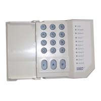
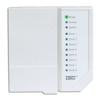
Mounting the Keypad
Keypads should be located close to the designated “Entry-
Exit” door(s) and mounted at a height convenient for all
users.
NOTE: Complete all wiring to the control panel before
applying AC power or connecting the battery.
Auxiliary Power
Connection
The auxiliary power supply can be
used to power keypads, motion
detectors and other devices that
require 12 VDC. See the Fire Zone
Wiring section for the connection
of 4-wire smoke detectors. The
total load for the auxiliary power
output must be calculated for all
devices connected across the
AUX +/- terminals and for devices connected between the
AUX + and PGM terminals. The output current cannot
exceed 475 mA.
PGM Terminal Connections
The PGM terminal is a switched
negative output which can be
controlled by various
programming options (See
Programming Guide Section
[24]). Devices controlled by the
PGM output must be connected
between the PGM terminal, which
is (-) and the Aux. (+) terminal.
Bell/Siren Connection
Wire run distances are in feet/ meters from the control panel to
the last device on the loop. Calculations are based on 12 VDC
at the panel with a maximum 10% voltage drop at the last
device. Observe polarity when connecting siren drivers, sirens
and polarized bells.
Keypad Wiring
Up to three keypads may be connected in parallel. Do not
connect multiple keypads on the same keypad wire run. For
Standby Loading purposes, use a current draw of 35 mA per
keypad. This represents the panel in the disarmed state with
two zones open.