6
NOTE:Only one NC contact can be connected to each zone.
Wiring multiple detection devices or contacts on a single loop
is not allowed.
The following chart shows zone status under certain condi-
tions:
Loop Resistance Loop Status
0Ω (shorted wire, loop shorted) Fault
5600Ω (contact closed) Secure
Infinite (broken wire, loop open) Tamper
11200Ω (contact open) Violated
End of Line Resistors. . . . . . . . . . . . . . . . . .Section [013]: [1]
Double End of Line Resistors . . . . . . . . . . .Section [013]: [2]
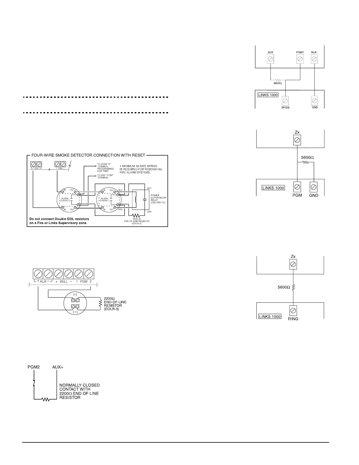
2.9 Fire Zone Wiring
NOTE:4-Wire Smoke Detectors
All fire zones must be wired according to the following dia-
gram:
2-Wire Smoke Detectors
The following 2-wire smoke detectors may be used: ESL429AT
and DSC MN220. If PGM2 has been programmed for a 2-wire
Smoke Detector connection
, the detectors must be wired
according to the following diagram:
NOTE:If PGM2 is programmed for 2-wire smoke support, the
connector JP1 on the main board must be removed.
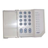
2.10 24-Hr Auxiliary Input Wiring (PGM2)
If PGM2 has been programmed for 24-hour operation, the
zone must be wired according to the following diagram:
NOTE:If PGM2 is pro-
grammed for 24-Hr Auxil-
iary Input support, the
connector JP1 on the
main board must be
removed.
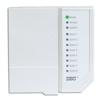
2.11 LINKS Zone Wiring*
LINKS Support
When using the LINKS1000
cellular communicator, con-
nect the LINKS to the main
panel according to the fol-
lowing diagram:
LINKS Supervision (24 Hour Supervisory)
When using the
LINKS1000 cellular com-
municator, any main board
zone may be configured
for LINKS Supervision. Pro-
gram this zone as zone
type [09], 24 Hour Supervi-
sory in section [001].
With a LINKS Supervisory
zone, if the LINKS1000
experiences a trouble, the
zone will be violated, caus-
ing the panel to report the
event to the central station.
This type of zone always
requires a single EOL
resistor (5600Ω).
Wire this zone according to the above diagram.
LINKS Answer
When using the LINKS1000
cellular communicator, any
main board zone may be
configured for LINKS
Answer.
A zone configured for
LINKS Answer allows
downloading to be per-
formed in the event of tele-
phone line failure. When
the LINKS receives a tele-
phone call, it will activate
the RING terminal on the
LINKS circuit board. The
zone programmed as
LINKS Answer always
requires a single EOL resis-
tor (5600Ω).
Wire the LINKS Answer zone according to the above diagram.
NOTE: The LINKS Answer zone is only required for download-
ing to the panel via the LINKS.
NOTE: When using the LINKS, Busy Tone Detection must not
be used.
NOTE: Keypad zones cannot be used for 24 Hour Supervisory
or LINKS Answer.
*Not investigated by UL.