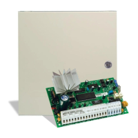
HOOKUP DIAGRAMS
38
BATTERY
12V 4.0Ah
GELL-CELL
max battery charge
current is 360 mA.
Battery capacity for
emergency is at least
4 hours.
BELL / SIREN
700 mA MAX
50 mA MAX
RED
BLK
YEL
GRN
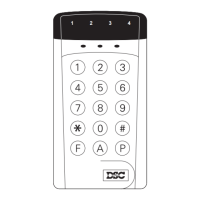
Refer to the instructions
on keypad wiring.
PC2550RK Keypad
(3 MAX)
AUXILIARY
SUPPLY
OUTPUTS
400 mA max.
T-1
R-1
TIP
RNG
GND
NO
AUX
BRN
GRY
GRN
RED
EEPROM RESET
RJ31X
CSA LISTED
16 VAC 40 VA
AC
AUX
GND
SW
AUX
BELL
RED
BLK
Nut
Washer
Cabinet
Bolt
Ground
Rod
+12V
+12V
SWITCHED
- AUX
AC POWER
TRANSFORMER
AUX
1 AMP
BATT
5 AMP
BELL
5 AMP
NC NO
YEL GRN
BLK RED
WHT
PGM OUTPUT RELAY
(Keypad [✱][7])
COM
PGM +AUX
RM-1
GROUND START
CIRCUIT
BLK RED
WHT
PGM +AUX
RNG
GRN
RM-1
NC
NO
End-Of-Line Resistors:
1KΩ 1/2 Watt
TYPICAL BURGLARY
ZONE CONNECTIONS
Normally Closed
contacts
Normally Open
contacts
4-wire Smoke
Detector Power
12 V
DC
400 mA max.
Alarm Initiating Loop
Resistance 100Ω MAX
RED
BLK
WHT
GRN
End-Of-Line Resistor
EOLR-1
Note: Smoke detector must be 4-wire
ULC listed latching type (ESL 446C).
To reset smoke detectors - press [✱]
then hold down key [4] for 2-3 sec.
Bell Loop 700 mA MAX
BELL
Smoke Detector Power
Supervision Relay (DSC RM-1)
12VDC 35mA
SW
AUX
BELL
FIRE
AUX
GND
TYPICAL FIRE ALARM
ZONE CONNECTIONS
In Out
In Out
Alarm
Contact
Note: All voltage outputs are
rated 12VDC unregulated.
Refer to Instruction Manual for
complete operating instructions.
Temperature Range:
0°C-49°C(32°F-120°F)
 Loading...