1
SPECIFICATIONS
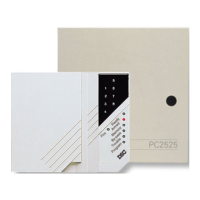
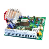
Control Panel Specifications
13 zones including:
• 8 fully programmable supervised zones (EOL resistors)
• Supervised fire zone
• 1 auxiliary normally open zone
• 3 keypad activated zones
Audible alarm output:
• Bell output
700 mA, fused at 5 Amps, 11 V
DC unregulated
• Steady or pulsed output
EEPROM memory:
• Does not lose codes or system status on complete AC
and battery failure
Programmable output:
• Transistor switch sinks 50 mA to ground
• Operation controllable through program options
Powerful 1.5 amp regulated power supply:
• 400 mA auxiliary supply, 11 V
DC unregulated
• Separately fused for battery, keypad/auxiliary supply
and bell output
• Supervision for loss of AC power, low battery
• Internal clock locked to AC power frequency
Switched Smoke Detector Supply Output:
• Controlled from keypad [✱][4] command
Battery required:
• 12 volt 4 Ah minimum rechargeable gel-cell or sealed
lead-acid battery
Transformer required:
• 16.5 VAC, 40VA
Dimensions:
• 11" x 11.8" x 3.3" deep (279 x 300 x 84 mm)
Weight:
• 6.5 lbs (3 kg)
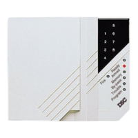
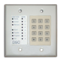
Remote Keypad Specifications
(PC2550RK)
• Four wire (QUAD) hook-up and up to 3 keypads per
system
• Built-in piezoelectric buzzer
• Full annunciation of zones and system status
• Nominal current draw 60 mA
• Dimensions 5.5" x 4.5" x 1" deep (140 x 114 x 25 mm)
Output Voltage Specification
Due to the requirements of standards UL985 and
UL1023, it is required to indicate an output voltage of 11
V
DC unregulated. Typically, with normal AC in and a fully
charged battery, the output voltage will be 13.8 V
DC. With
AC off and a discharged battery, the voltage will go to 10
volts. Devices that require power from the control panel
should be capable of normal operation over the voltage
range of 10 to 14 V
DC.
Digital Communicator Specifications
• 76 reporting codes
• Transmits all 10BPS and 20BPS single line and
extended formats
• Radionics Rounds and Radionics Parity formats
• Sescoa Superfast format
• 3/1, 4/2 and hexadecimal numbers
• DTMF and Pulse dialing
• DPDT line seizure
• True dial tone detection
• Anti-jam feature
• Two telephone numbers and two account codes
• Split reporting of selected transmissions to each
telephone number
WWW.DIYALARMFORUM.COM