EasyManua.ls Logo

DSC MAXSYS PC4010 User Manual

DSC MAXSYS PC4010
36 pages
To Next Page IconTo Next Page
Page #1 background imageLoading...
Page #1 background image
Security Products
TM
©1998 Digital Security Controls Ltd.
Printed in Canada 29003126 R0
WARNING: This manual contains information on limitations
regarding product use and function and information on the
limitations as to liability of the manufacturer. The entire
manual should be carefully read.
PC4010 v3.0 • Instruction Manual
AVIS: L’étiquette de l’Industrie Canada identifie le
matériel homologué. Cette étiquette certifie que le
matériel est conforme à certaines normes de protection,
d’exploitation et de sécurité des réseaux de
télécommunications. Industrie Canada n’assure
toutefois pas que le matériel fonctionnera à la
satisfaction de l’utilisateur.
Avant d’installer ce matériel, l’utilisateur doit s’assurer
qu’il est permis de le raccorder aux installations de
l’entreprise locale de télécommunication. Le matériel
doit également être installé en suivant une méthode
acceptée de raccordement. L’abonné ne doit pas
oublier qu’il est possible que la conformité aux
conditions énoncées ci-dessus n’empêchent pas la
dégradation du service dans certaines situations.
Les réparations de matériel homologué doivent être
effectuées par un centre d’entretien canadien autorisé
désigné par le fournisseur. La compagnie de
télécommunications peut demander à l’utilisateur de
débrancher un appareil à la suite de réparations ou
de modifications effectuées par l’utilisateur ou à cause
de mauvais fonctionnement.
Pour sa propre protection, l’utilisateur doit s’assurer
que tous les fils de mise à la terre de la source d’énergie
électrique, les lignes téléphoniques et les canalisations
d’eau métalliques, s’il y en a, sont raccordés ensemble.
Cette précaution est particulièrement importante dans
les régions rurales.
AVERTISSEMENT: L’utilisateur ne doit pas tenter
de faire ces raccordements lui-même; il doit avoir
recours à un service d’inspection des installations
électriques, ou à un électricien, selon le cas.
L’indice de charge (IC) assigné a chaque dispositif
terminal indique, pour éviter toute surcharge, le
pourcentage de la charge totale qui peut être raccordée
à un circuit téléphonique bouclé utilisé par ce
dispositif. La terminaison du circuit bouclé peut être
constituée de n’importe quelle combinaison de
dispositifs, pourvu que la somme des indices de charge
de l’ensemble des dispositifs ne dépasse pas 100.
L’Indice de charge de ce produit est 0.1B.
NOTICE: The Industry Canada label identifies
certified equipment. This certification means that the
equipment meets certain telecommunications network
protective, operational and safety requirements.
Industry Canada does not guarantee the equipment
will operate to the user’s satisfaction.
Before installing this equipment, users should ensure
that it is permissible to be connected to the facilities of
the local telecommunications company. The
equipment must also be installed using an acceptable
method of connection. The customer should be aware
that compliance with the above conditions may not
prevent degradation of service in some situations.
Repairs to certified equipment should be made by an
authorized Canadian maintenance facility designated
by the supplier. Any repairs or alterations made by
the user to this equipment, or equipment malfunctions,
may give the telecommunications company cause to
request the user to disconnect the equipment.
User should ensure for their own protection that the
electrical ground connections of the power utility,
telephone lines and internal metallic water pipe
system, if present, are connected together. This
precaution may be particularly important in rural
areas.
CAUTION: Users should not attempt to make such
connections themselves, but should contact the
appropriate electric inspection authority, or electrician,
as appropriate.
The Load Number (LN) assigned to each terminal
device denotes the percentage of the total load to be
connected to a telephone loop which is used by the
device, to prevent overloading. The termination on a
loop may consist of any combination of devices subject
only to the requirement that the total of the Load
Numbers of all the devices does not exceed 100.
The Load Number of this unit is 0.1B.

Other manuals for DSC MAXSYS PC4010

Question and Answer IconNeed help?

Do you have a question about the DSC MAXSYS PC4010 and is the answer not in the manual?

DSC MAXSYS PC4010 Specifications

General IconGeneral
BrandDSC
ModelMAXSYS PC4010
CategorySecurity System
LanguageEnglish

Summary

Introduction

About Your Security System

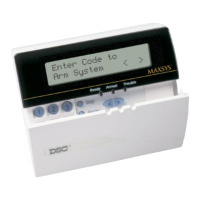
Provides an overview of the DSC security equipment, its features, and user interaction via the LCD keypad.

About this Manual

Details the manual's purpose, content coverage, and advises on distributing specific sections to general users.

Fire Detection

Explains the system's capability to monitor fire detection devices and provide warnings, emphasizing proper installation.

Monitoring

Describes the system's ability to transmit alarms and information to a monitoring station over telephone lines.

Section 1: General System Operation

1.1 Getting to Know Your System

Introduces the components of the security system: control panel, keypads, detectors, zones, partitions, and access codes.

1.2 How to Arm

Details the procedure for arming the system, including single and multi-partition arming, and exit delays.

1.3 Alternate Arming Methods

Explains different arming modes like Away, Stay, and Arming Without Entry Delay, and the Quick Arm feature.

1.4 Disarming

Covers the process of disarming the system, including handling entry delay and disarming multiple partitions.

1.5 Alarm Memory

Instructs on how to view alarms that occurred during the last armed period and how to exit alarm memory mode.

1.6 If An Alarm Sounds

Describes how fire and intrusion alarms are indicated and how to respond to them, including silencing and checking the source.

1.7 Zone Bypassing

Explains how to temporarily disable zones for system arming and the implications of bypassing zones.

1.8 Trouble Conditions

Details how to identify and address various system trouble conditions, such as AC power loss or TLM trouble.

Section 2: Access Codes

2.1 Program A New Access Code

Guides on programming new access codes, including selecting a code, entering the code, and assigning a user name.

2.2 Modify an Existing Code

Explains methods to search for and modify existing access codes using user number or user name.

2.3 Change User Code Options

Details how to change user code options, determining system features accessible by a specific code.

2.4 Access Code Label Options

Describes options available when programming access code labels, such as clearing text and changing case.

2.5 Delete an Existing Code

Provides instructions for erasing access code data and the access code label separately.

2.6 Special Codes

Defines special codes like System Master, Supervisor, Duress, and One-time Use codes and their functions.

2.7 Installer Programmed Codes

Lists codes programmed by the installer, such as Second Master, Walk Test, and Guard codes.

Section 3: System Administration

3.1 Quick Arm

Enables arming the system with a single key press instead of an access code.

3.2 Quick Exit

Allows users to exit the premises during an exit delay without causing an alarm.

3.3 Auto Arm Control

Details how to enable and configure automatic daily arming and scheduled arming/disarming.

3.4 Setting the Time and Date

Provides instructions for setting the system's current time and date.

3.5 Activating Door Chime

Explains how to enable the door chime feature, which alerts users when doors are opened or closed.

3.6 View Event Buffer

Guides on accessing and viewing the system's event log, showing recent system activities.

3.7 [*][7] Command Outputs 1-8

Describes how to activate system outputs like lights or door strikes using specific keypad commands.

3.8 Keypad Control

Covers adjusting keypad backlighting brightness and display contrast settings.

3.9 Downloading Options

Explains how to enable the DLS Window for remote downloading and system access.

Section 4: Access Control

4.1 Access Card Readers

Details how to use access card readers, the meaning of status lights, and audible indicators.

4.2 Access Card Programming

Covers programming access cards for existing users and new users, including card numbers and access levels.

4.3 Search Using Access Card Numbers

Explains how to search for users or access cards using their respective numbers.

Section 5: Testing and Maintenance

5.1 Walk Test

Details how to perform a walk test to verify the functionality of detectors on a partition, including various test options.

5.2 System Test

Describes how to conduct a system test that activates the bell/siren and sends a test transmission to the monitoring station.

5.3 Lamp Test (PC4216)

Explains how to test the PC4216 output module by activating all connected outputs for two seconds.

5.4 System Maintenance

Provides essential maintenance tips, including keypad cleaning, battery replacement recommendations, and device care.

Section 6: Fire Safety

6.1 Fire Alarm Operation

Explains fire alarm sounds, how to silence bells, and how to reset fire zones after an alarm.

6.2 Guidelines for Locating Smoke Detectors

Offers guidance on the optimal placement of smoke detectors in residential units for maximum effectiveness.

6.3 Household Fire Safety Audit

Provides a checklist for conducting a household fire safety audit, focusing on electrical safety and storage of hazardous materials.

6.4 Fire Escape Planning

Emphasizes the importance of developing and rehearsing fire escape plans, including considerations for accessibility and assembly points.

Appendix A – Special Characters

Related product manuals