Do you have a question about the DSC maxsys PC4020KT and is the answer not in the manual?
Details on the system's limits for zones, outputs, keypads, etc.
Information about the VPM for user feedback and system control.
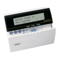
Features and usage of the LCD4500 remote keypad.
Explanation of the 211 output capabilities and configurations.
Details on the programmable switched auxiliary output function.
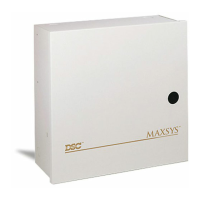
Overview of the available system enclosures and their capacities.
Information on the supervised alarm output for sirens.
Description of the event buffer for logging system activities.
Details on dividing the system into up to 8 independent partitions.
Information on using the PC4400 for printer connectivity.
Overview of the PC4820 module for access control functions.
Explanation of the system's non-volatile memory retention.
Description of user-configurable options available on keypads.
Details on the system's communication capabilities and formats.
Information regarding LINKS support and auto-programming.
Guide for planning and executing system installation and wiring.
First step in installation, focusing on drawing the building layout.
Overview and testing of RF zones and their placement.
Guidelines for placing system components for optimal performance.
Procedure for testing RF signal strength for zone placement.
Information on wireless PIR motion detector features and testing.
Explanation of zone supervision for wireless zone communication.
Description of battery trouble conditions and their indications.
Procedure for restoring battery troubles and tamper conditions.
Process for defaulting serial numbers and erasing RF signatures.
Details on COMBUS power, operation, and troubleshooting.
Steps for testing COMBUS voltage and identifying low voltage issues.
Instructions for safely mounting the main control panel cabinet.
Overview of the system programming process and partition setup.
Information on the installer code and its role in system programming.
Procedure for resetting the panel to factory default settings.
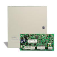
Specifications for the PC4020 main control panel features.
Details on the control panel's output voltage range and behavior.
Specifications for the remote keypad's functionality and dimensions.
Specifications for the PC4108 8-zone expansion module.
Specifications for the PC4116 16-zone expansion module.
Specifications for the PC4164 64-zone wireless expansion module.
Specifications for the PC4204 high current output module.
Specifications for the PC4216 low current output module.
Specifications for the PC4400 RS-232 interface for printers.
Specifications for the PC4700 fire alarm module.
Specifications for the LCD4500 remote keypad.
Specifications for the Escort 4580 voice prompting module.
Specifications for the PC4820 access control module.
Visual guide for connecting the PC4020 control panel.
Details on connecting AC power to the PC4020 panel.
Information on using auxiliary power terminals for devices.
Details on the switched auxiliary power terminals.
Wiring instructions for bell and siren outputs.
Explanation of the programmable output terminal (PGM).
Connection details for the COMBUS communication bus.
Wiring for zone input terminals, including EOL configurations.
Wiring instructions for telephone line connections.
Guidelines for correctly connecting the system battery.
Overview of the LCD4500 keypad's functions and interface.
Explanation of system partitions and zone assignment.
Details on how access codes function within the system.
Explanation of global keypad functionality across partitions.
Functions available to System Master Code users.
Information on the installer code and its role in system programming.
Procedure and conditions for arming the security system.
Procedure for disarming the security system.
How to use auto-bypass and home-away arming features.
Steps and options for bypassing individual zones.
How to view and interpret system trouble conditions on the keypad.
How to access and view the system's alarm memory.
Commands for programming user access codes and options.
Guide for adding/modifying access codes via master/supervisory codes.
How to search for users by name for programming.
How to search for users by card number for programming.
Accessing and using various user-configurable functions.
Function to initiate a call to the downloading computer.
Performing a lamp test on PC4216 modules.
Procedure for performing system walk tests.
Activating programmed utility outputs from the keypad.
Overview of commands for installer-level system programming.
Using the "At-Home" arming mode with zone bypassing.
Using the Quick Arm feature for faster system arming.
Using the Quick Exit feature for leaving the premises after arming.
Activating specific keypad zones like Fire, Auxiliary, Panic.
Explanation of LED indicators on access card readers.
How the buzzer operates for access control events.
Steps for programming and using access cards.
Using access cards to arm and disarm system partitions.
How to postpone automatic arming using an access card.
Functionality of the Request To Exit (REX) input.
Steps to configure the printer for serial communication.
Procedure for downloading system data via phone lines.
Procedure for downloading system data using a local computer.
Reference table for available ASCII characters for labels.
Table listing diagnostic codes and their meanings.
| Model | PC4020KT |
|---|---|
| Type | Security System |
| Battery Backup | 12V 7Ah |
| Event Log | 1000 events |
| Zones | 8 |
| Power Supply | 16.5VAC, 40VA |
| Keypad Support | LCD, LED |