TABLE OF
CONTENTS
Introduction _______________________________________________________________ 1
System Overview _________________________________________________________ 2
Maximum System Capabilities .................................................................................................. 2
128 Programmable Zones ......................................................................................................... 2
Voice Prompting Module (VPM) ................................................................................................ 2
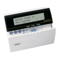
LCD Keypads (LCD4500) ......................................................................................................... 2
211 Outputs ............................................................................................................................... 2
Switched Auxiliary Output ......................................................................................................... 2
4 Enclosures .............................................................................................................................. 2
Supervised Alarm Output .......................................................................................................... 2
Event Buffer ............................................................................................................................... 2
8 True Partitions ......................................................................................................................... 2
RS-232 Interface Module (PC4400) .......................................................................................... 2
PC4820 Access Control Module ............................................................................................... 2
Internal Memory ......................................................................................................................... 2
Keypad User Options ................................................................................................................ 2
Communicator ........................................................................................................................... 2
LINKS Support ........................................................................................................................... 2
Installation and Wiring____________________________________________________ 3
Suggested Wiring Procedure .................................................................................................... 3
RF Zones — Summary ............................................................................................................... 4
RF Signal Test ............................................................................................................................ 4
Wireless PIR Motion Detectors .................................................................................................. 4
Zone Supervisories .................................................................................................................... 4
Battery Troubles ........................................................................................................................ 5
Restoring Battery Troubles ........................................................................................................ 5
Default Srl #'s (4) ....................................................................................................................... 5
COMBUS Power and Operation ................................................................................................ 5
Testing The Combus ................................................................................................................. 5
Mounting the Panel .................................................................................................................... 6
Programming the System ..........................................................................................................6
Hardware Reset of Memory to Factory Defaults ....................................................................... 7
PC4020 Main Board Specifications _______________________________________ 8
Control Panel ............................................................................................................................. 8
Output Voltage ........................................................................................................................... 8
Remote Keypad ......................................................................................................................... 8
Module Specifications ____________________________________________________ 9
PC4108 Expansion Module ....................................................................................................... 9
PC4116 Expansion Module ....................................................................................................... 9
PC4164 Expansion Module ....................................................................................................... 9
PC4204 High Current Output Module ....................................................................................... 9
PC4216 Low Current Output Module ........................................................................................ 9
PC4400 RS-232 Interface Adapter Module .............................................................................. 9
PC4700 Fire Module .................................................................................................................. 9
LCD4500 Remote Keypad ........................................................................................................ 9
Escort 4580 (Voice Prompting Module) .................................................................................... 9
PC4820 Access Control Module ............................................................................................... 9
PC4020 Control Panel Wiring Diagrams _________________________________ 10
Module Hookup Diagram ......................................................................................................... 11
Terminal Connections ___________________________________________________ 13
“AC” Power Terminals .............................................................................................................. 13
Auxiliary Power Terminals “AUX” and “GND” .......................................................................... 13
Switched Auxiliary Power Terminals ........................................................................................ 13
Bell/Siren Terminals .................................................................................................................. 13
Programmable Output Terminal “PGM” ................................................................................... 13
COMBUS Terminals “RED”, “BLK”, “YEL” and “GRN” ............................................................ 13
Zone Input Terminals “Z1” to “Z16” ......................................................................................... 13
Telephone Terminals “TIP”, “RNG”, “T-1” and “R-1” ............................................................... 14
Battery Connections ................................................................................................................. 14