EasyManua.ls Logo

DSC PC4820

DSC PC4820
16 pages
To Next Page IconTo Next Page
Loading...
1
S e c t i o n 1
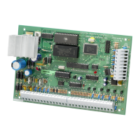
The PC4820 is a versatile Dual Card Reader Access Control
module which will enable you to meet the most
demanding access control requirements of an installation.
The PC4820 is monitored and programmed via the
PC4010/4020 control panel. Up to 16 PC4820 modules can
be connected to a PC4010/4020 via a 4-conductor Combus,
using standard, unshielded station wire.
Each PC4820 is capable of providing supervision for two
door inputs which may to assigned to any PC4010/4020
zone. Each door contact may be configured for any zone
end of line option which the control panel can provide.
Each of the two PC4820 Access Card Readers can be
programmed to function independently on different
doors, or together controlling access for both sides of one
door.
Control of the access points can be performed using a
variety of equipment. The PC4820 supports four different
types of card readers: the Polaris magnetic strip reader,
the Shadow Prox proximity card reader, the HID proximity
readers, and 26-bit standard Wiegand card readers. The
PC4820 also supports the use of any request to exit device
including the T-REX exit detector.
1.1 PC4820 Access Control Module
Specifications
Two Zone Inputs
Two programmable supervised zones ( EOL resistors
– value )
Zones may be programmed as Standard or Auxiliary
delay zone types
PC4010/4020: up to 16 PC4820 can be added (up to
32 access points)
Non Volatile RAM (internal memory)
Does not lose any system programming when the
module is powered down.
Low Current Outputs
Six low current outputs (open collector outputs
switched to ground 25mA max.) :
Two LED terminals - To the LED input of the
reader
Two BUZ terminals - To the Buzzer input of the
reader
Two OUT terminals - Reserved for future use
Regulated Power Supply ( 1.5 Amp max. )
Electronic shutdown protection of the battery,
auxiliary output, 5 and 12 V reader power supplies,
and lock device power output
Auxiliary output supply: 12V
DC, 125mA Max
LK1 and LK2 Door Strike power: 12V
DC, 250mA Max
Reader Power 5V
DC, 125mA Max
Reader Power 12V
DC, 125mA Max
Reader Technology
Polaris, Shadow Prox, HID Proximity and 26-bit
Standard Weigand format
Access Card Compatibility
Polaris POL-C1CN - Polaris Magnetic Cards
Shadow Prox, Module Numbers:
SH-C1 - Shadow Prox Card
SH-K1 - Shadow Prox Keytag
HID Proximity:
HID-C1325KSF - Proximity Card
HID-C134KSP - Proximity Keytag
Weigand - Standard 26 bit formats
Battery
12V
DC 7.0Ah recommended rechargeable gel-cell
Transformer
16.5 V
AC, 40VA
Operating Temperature
•2
°
C to 40
°
C (35
°
F to 110
°
F) operational Temperature
Range
•90
°
non-condensing humidity
Output Voltage
Output voltage = 13.8V
DC (with normal AC and a
fully charged battery). Devices that require power
from the PC4820 should be capable of operation over
the voltage range of 10 to 14V
DC.
5V Power Supply - Devices connected to the 5V
supply should be capable of operation between 4 and
6V.
Introduction
Question and Answer IconNeed help?

Do you have a question about the DSC PC4820 and is the answer not in the manual?

DSC PC4820 Specifications

General IconGeneral
BrandDSC
ModelPC4820
CategoryCard Reader
LanguageEnglish

Summary

Introduction

PC4820 Access Control Module Specifications

Details the technical specifications of the PC4820 module, covering its features and capabilities.

Installation and Wiring

Plan Your Installation

Outlines the initial planning steps for installing the access control system, including layout and component placement.

Installation Steps

Covers the procedural steps for installing the PC4820 module and related devices, including mounting and connections.

Inputs - POST, ARM and REX

Describes the function and wiring of POST, ARM, and REX inputs for system control and events.

Outputs - LED, BUZ and OUT Terminals

Explains the configuration and use of LED, BUZ, and OUT output terminals for reader feedback and other functions.

Door Locking Devices - LK1 & LK2 Terminals

Details the connection and operation of door locking devices via LK1 and LK2 terminals.

Access Card Readers

Covers the installation and configuration of access card readers for door access control.

Installation and Wiring - Continued

Outputs - LED, BUZ and OUT Terminals

Details the function of LED, BUZ, and OUT terminals for reader feedback and system status.

Door Locking Devices - LK1 & LK2 Terminals

Discusses the operation of door locking devices and their limitations, including fail-safe/secure modes.

Access Card Readers

Explains dual reader setup, reader mounting height, and keypad reader integration.

Installation and Wiring - Reader Details

Access Card Readers

Covers reader types, connection charts, and compatibility with different card formats.

PC4820 Connection Chart

Table detailing specific reader connections to PC4820 terminals and functions.

PC4820 List of Supported Readers and Cards

Lists compatible reader types and corresponding card part numbers.

Cabling Specifications

Provides guidelines for maximum wire lengths and cable types for system connections.

PC4820 Access Control Module Reader Connections

Diagrams showing specific reader connection configurations for various reader types.

Installation and Wiring - Diagrams

PC4820 Access Control Module Reader Connections

Illustrates Polaris, Shadow Prox, and HID reader connections to the PC4820 module.

Connecting External Power Supplies

Illustrates how to connect external power supplies to the PC4820 system.

Programming the PC4820

Programming Reader Types

Selects the type of access card reader to be used with the module for each door.

Reader Options

Configures various reader operational parameters and behaviors like REX or LED indicators.

Arming and Disarming with Access Cards

Sets up arming/disarming and auto-arm postponement via access cards presented at readers.

Programming the PC4820 - Schedules & Zones

Arming and Disarming with Access Cards

Details partition mask and schedule requirements for arming/disarming functions.

Door Times

Sets parameters for door unlock duration and door open time limits.

Zone Assignment for Access Doors

Assigns PC4820 doors to specific zones on the PC4010/4020 control panel.

Access Door Schedules

Configures date schedules for various access door features and events.

Programming the PC4820 - Advanced Options

Door Times

Details Door Unlock Schedule and Door Open Time parameters.

Zone Assignment for Access Doors

Discusses supervision options and zone assignment for access doors.

Access Door Schedules

Covers Code Schedule, Forced Open Schedule, and Forced Open Bell Schedule.

Access Level

Defines access levels and their association with date schedules for user permissions.

Programming the PC4820 - Card Access

Access Level

Explains programming of access levels and their respective date schedules.

Programming Access Cards

Outlines the process for programming access cards into the PC4010/4020 system.

Diagnostics

Hardware Reset

Procedure for resetting the PC4820 to factory default settings.

Diagnostics via VTAL LED (L1)

Interprets LED indicators for system diagnostics and fault conditions.

PC4820 Programming Worksheet

Limited Warranty

FCC Compliance Statement

PC4820 Access Control Module Wiring Diagram