4
code for the access card used, otherwise access will not
be granted, even if the code entered is a valid code on the
system. When access is denied to the user due to a wrong/
invalid code being entered, or time has expired waiting
for the access code, the LED on the reader will flash 3 times
every second and the buzzer will give an audible beep 3
times every second to indicate that access was denied.
Reader LED Flash Rates
Most access card readers will have an LED output to
provide visual feedback when the access card is presented
to the reader. The light will flash in different ways to
indicate the following conditions:
LED State Access Condition
Steady Red Door is locked
Steady Green Door is unlocked –
Access granted
Slow flash (state changes The partition that the
every half second) Arm/Disarm mask is
assigned to is armed
Medium Flash (state changes Waiting for a Privileged
three times every second) card to be presented
Fast flash (State change Access denied/Time
four times every second) expired waiting for a
privileged card.
Buzzer Operation
Most access card readers will have a buzzer output to
provide audible feedback. The Buzzer output may be
connected to operate local warning devices for the
following conditions:
• The access controlled door has been forced open.
The buzzer will activate and remain active until the
door has been closed.
• The access controlled door has been left open too
long. The buzzer will activate and remain active
until the door has been closed. The buzzer will pulse
on and off for the last half of the programmed Door
Open Time to indicate that the Door Open Too Long
event is about to occur.
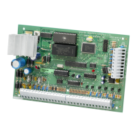
Reader Connection Function PC4820 Terminal
Polaris / Shadow Prox HID
Green Green Data 0 GRN
White White Data 1 WHT
Red Red + V
DC or +12VDC +5V or +12V
Black Black Ground GND
Blue Yellow Buzzer Buzz
Brown Brown (Red LED) LED LED
Orange/Yellow Terminals marked as Tamper Switch To PC4010/4020 zone or connected
(Polaris only) Tamper Common in series with the assigned door
& Tamper Select* input on this module (optional)
——— Blue Hold Not used
——— Orange Green LED Not used
——— Violet Return GND
Purple/Grey (POL-2KP only) -------- Independent Switch Can be used for Arm
or Post inputs. See PC4820 Wiring
Diagram for wiring instructions.
* Tamper connection not available on the MiniProx detector
PC4820 Connection Chart
Reader Type Reader Part Numbers Supply Voltage Card Part Numbers
Magnetic Stripe POL-1, POL-1W, POL-2, POL-2KP +5Vdc POL-C1CN
Bar Code BC-201
Proximity:
Shadow Prox SH-1, SH-2, SH-2KP +5Vdc to 14Vdc SH-C1, SK-K1, SH-CMG1,
SH-4, SH-5 +12Vdc SH-CMG2
SH-6, SH-7 +24Vdc to 28Vdc
HID HID-MP5365 - MiniProx +12Vdc HID-1365KSF, HID-1335KSF,
HID-PR5355, HID-PR5355KP - ProxPro +10Vdc to 15Vdc HID-1334KSF, HID-1365KSF,
HID-MX5375 - MaxiProx +14Vdc to 28.5Vdc HID-1385KSF
PC4820 List of Supported Readers and Cards

 Loading...