2
PROGRAMMING GUIDE 11
Sections [05] through [07]: Selecting System Functions ..................................................................... 11
HEX Data Programming ........................................................................................................................ 11
Resetting Programming to the Factory Default Settings....................................................................... 11
PROGRAMMING SECTIONS 12
[01] Zone Definitions ............................................................................................................................ 12
[02] System Times ................................................................................................................................ 13
[03] Installer’s Code ............................................................................................................................. 13
[04] Programmable Output Options (PGM OUT Terminal) .................................................................. 13
[05] 1st System Option Code ............................................................................................................... 14
[06] 2nd System Option Code .............................................................................................................. 14
[07] 3rd System Option Code............................................................................................................... 15
[08] First Phone Number ...................................................................................................................... 16
[09] Second Phone Number ................................................................................................................. 16
[10] Customer Account Code .............................................................................................................. 16
Disabling Communications ................................................................................................................... 16
[11] Zone Alarm and Restoral Reporting Codes .................................................................................. 16
[12] Closing and Opening Reporting Codes ....................................................................................... 16
[13] Maintenance and Priority Codes................................................................................................... 17
[14] Downloading Access Code .......................................................................................................... 17
FOR THE RECORD 18
PROGRAMMING WORKSHEETS 19 - 22
HOOK-UP DIAGRAM 23
LIMITED WARRANTY 24
HOOK-UP DIAGRAM
23
AUX 1 AMP
BELL 5 AMP
BATT 5 AMP
DO NOT REPLACE FUSES
WITH HIGHER VALUES
THAN SHOWN
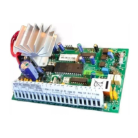
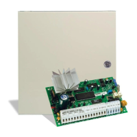
PC560
12VDC BELL/SIREN
1A MAX.
OBSERVE POLARITY!
BATTERY
12V 4Ah
GELL CELL
+
RED BLK
Recognized limited energy cable should be used. Observe local codes as defined by the authority having jurisdication.
Refer to Installation and Instruction Manuals for complete operating instructions.
Detection devices that require power from the Control Panel should operate over the range of 10.0 to 14.0 VDC.
The DSC BRAVO models are recommended motion detectors. The DSC DG-50 is a recommended glassbreak detector.
Temperature Range: 0˚C to 49˚C (32˚F to 120˚F). Maximum Humidity: 85% relative humidity
INCORRECT CONNECTIONS MAY RESULT IN FUSE FAILURE
OR IMPROPER OPERATION. INSPECT WIRING AND ENSURE
CONNECTIONS ARE CORRECT BEFORE APPLYING POWER.
Before disconnecting the power supply from a general purpose
outlet socket, disconnect the telecommunications line plug.
YEL
BLK
GRN
RED
TLM-1
TELEPHONE
PLUG
TRANSFORMER
16VAC 20VA MIN.
DO NOT CONNECT TRANSFORMER
TO SWITCHED RECEPTACLE.
RECOMMENDED TRANSFORMER:
BASLER ELECTRIC BE 116240CAA-0002
240 VAC
50 Hz
GRN
YEL
BLK
RED
BATTERY CAPACITY FOR EMERGENCY STAND-BY IS AT
LEAST 4 HOURS IF THE TOTAL LOAD (BELL & AUX OUTPUTS)
IS 800mA OR LESS. BATTERY CHARGE CURRENT IS 360mA MAX.
RECOMMENDED BATTERY: YUASA NP4-12.
LOAD
300mA MAX.
LOAD
50mA MAX.
TO AUX+
TO AUX+
STR (STROBE)
OUTPUT
PROGRAMMABLE
OUTPUT
REFER TO
ZONE CONNECTIONS
BELOW
Z1
COM Z2
NC
NO
NC
NC
END OF LINE
RESISTOR
5600Ω 0.5W
END OF LINE
RESISTOR
5600Ω 0.5W
EOL RESISTOR
LOOPS USING
NO & NC
DEVICES
EOL RESISTOR
LOOPS USING
NC DEVICES
ONLY
KEY
COM
END OF LINE
RESISTOR
5600Ω 0.5W
MOMENTARY OR
MAINTAINED CONTACT
KEYSWITCH
PROGRAM KEY TERMINAL
CONFIGURATION IN SECTION [05].
IF KEY TERMINAL IS TO BE USED
AS A TAMPER ZONE, CONNECT THE
ZONE AS SHOWN IN THE "TYPICAL
BURGLARY ZONE CONNECTIONS"
DIAGRAM.
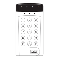
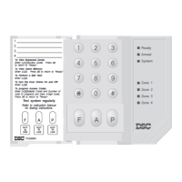
PC500RK KEYPAD SL-40 KEYPAD
Zone 1
Zone 2
Zone 3
Zone 4
Armed
System
Ready
OR
3 MAXIMUM PER SYSTEM
TO COM:
5600Ω 0.5W END OF LINE RESISTOR MUST BE
CONNECTED BETWEEN KEY AND COM TERMINALS
IF KEY TERMINAL IS NOT USED