5
Wiring
NOTE: Complete all wiring to the control panel before applying battery or AC power.
Burglary Zone Wiring
Burglary zone definition, (for example, Delay, Instant, 24-Hour, and so on) is programmed using the keypad.
Refer to Programming Guide Section [01].
NOTE: To help prevent false alarms, all zones are automatically bypassed for 120 seconds on power-up to allow
detectors to settle.
Wire
Gauge
1900 / 579
3000 / 914
2400 / 1493
6200 / 1889
7800 / 2377
24
22
20
19
18
Maximum wire length to
End of Line Resistor
(feet/meters)
Figures are based on maximum loop
resistance of 100 ohms.
Burglary Zone Wiring Chart
[06] 2nd System Option Code Page 14
Default Zone Light ON Zone Light OFF
OFF Zone Light 1 Private Line 40 BPS 4/2 with parity
ON Zone Light 2 1400Hz Handshake 2300Hz Handshake
OFF Zone Light 3 DLS Answer enabled DLS Answer disabled
OFF Zone Light 4 Ringback enabled Ringback disabled
If the communication format is changed:
when programming is complete, remove all power from the
system, wait for 10 seconds, and then restore power to the system.
[07] 3rd System Option Code Page 15
Default Zone Light ON Zone Light OFF
OFF Zone Light 1 Swedish Pulse Dialing Standard Pulse Dialing
OFF Zone Light 2
For Future Use
OFF Zone Light 3
For Future Use
OFF Zone Light 4
For Future Use
[08] First Phone Number Page 16
Enter [0] for the digit 0 in the phone number. Enter [
∗
4
∗
] (HEX D) for a 2-second pause between number
digits. Enter [#] to end the phone number entry.
If only one phone number is to be used, program the number in Section [08].
[09] Second Phone Number Page 16
[10] Customer Account Code Page 16
Enter [
∗
1
∗
] (HEX A) for the digit “0” in the account code. For a 3-digit code, enter [0] for the 4th digit.
20
Z1
COM Z2
NC
NO
NC
NC
END OF LINE
RESISTOR
5600Ω 0.5W
END OF LINE
RESISTOR
5600Ω 0.5W
EOL RESISTOR
LOOPS USING
NO & NC
DEVICES
EOL RESISTOR
LOOPS USING
NC DEVICES
ONLY
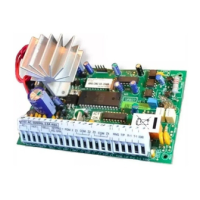
Auxiliary Power Connection
The Auxiliary Power Supply can be used to power motion detectors and other devices that require 12 VDC. The
total load for the Auxiliary Power Supply must be calculated for all devices connected across the AUX+ and
AUX-, AUX+ and STR terminals, and for devices connected between the AUX+ and PGM terminals. The output
current cannot exceed 800 mA when using a 40VA transformer.
PGM OUT Terminal Connection
The PGM OUT terminal is a switched negative output which can be controlled by various programming options;
refer to Programming Guide Section [04]. Devices controlled by the PGM OUT terminal must be connected
between the PGM OUT terminal and the AUX+ terminal.
PC560 v1.0A