4
INSTALLATION
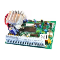
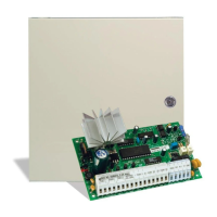
Mounting the Control Panel
Select a dry location close to an unswitched AC source, a ground connection, and the telephone connection.
Remove the printed circuit board, mounting hardware and keypad from the cardboard retainer inside the
control panel cabinet. Before attaching the cabinet to the wall, press the four white nylon printed circuit board
mounting studs into the raised mounting holes from the back of the cabinet. Also, secure the ground screw to
a hole in the cabinet.
Hold the cabinet in position and pull all wires into the cabinet. Mount the cabinet securely to the wall using the
mounting screws provided. It is recommended that appropriate wall anchors be used when securing the
cabinet to drywall, plaster, concrete, brick or other similar surfaces.
Press the PC560 Control Panel onto the nylon mounting studs. Pull all cables into the cabinet and prepare them
for connection.
Mounting the Keypad
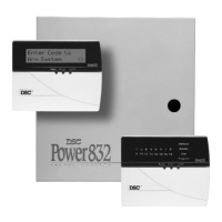
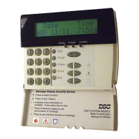
The PC560 Control Panel is controlled with the PC500RK or SL-40 Keypad. The Keypad should be located close
to the designated “Entry-Exit” door and mounted at a height convenient for all users.
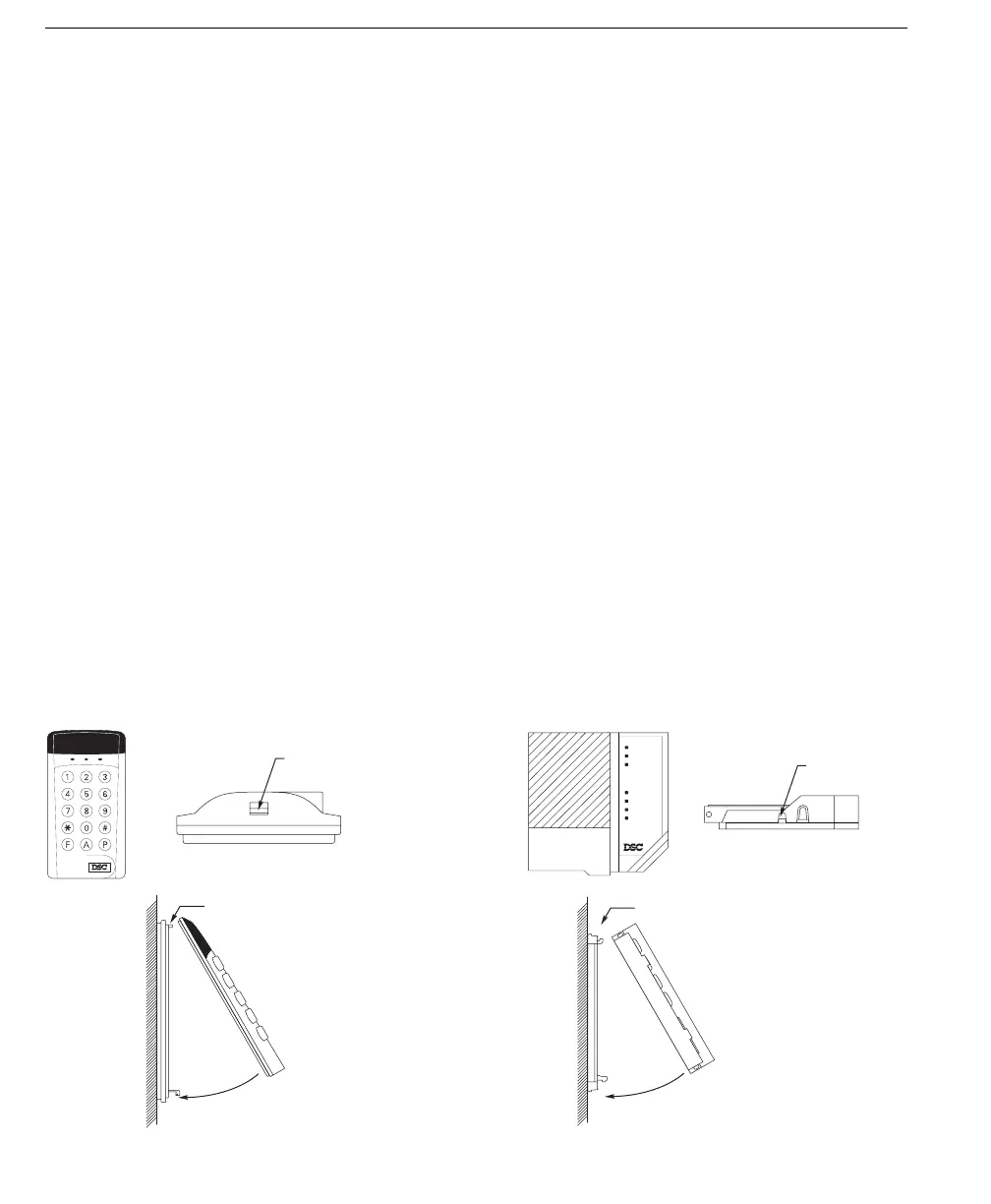
Disassemble the keypad by pressing gently on the locking tab found on the bottom of the unit. With the tab
disengaged, pull the backplate from the keypad.
Prepare a hole in the wall at the desired location and pull the keypad wiring through the hole. Hold the backplate
in position and pull the wires through the large opening in the backplate. Mount the backplate to the wall using
the hardware provided; it is recommended that plastic wall anchors be used. When mounting the backplate,
ensure that it is straight and level.
Prepare all wires for connection and connect the keypad wires to the in-wall wiring; refer to the Wiring Diagram
in the back of this manual.
Align the keypad with the mounting tabs on the top of the backplate. With the top mounting tabs engaged, swing
the keypad down and engage the bottom locking tab. Ensure that the top mounting tabs and the bottom locking
tab are securely engaged.
LOCKING TAB
SL-40 KEYPAD
BOTTOM VIEW
RE-ASSEMBLY OF
SL-40 KEYPAD
SIDE VIEW
(WIRES NOT SHOWN
FOR CLARITY)
ENGAGE TOP TABS FIRST
SWING KEYPAD DOWN
TO ENGAGE LOCKING TAB
WALL
LOCKING TAB
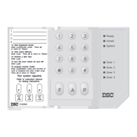
PC500RK KEYPAD
BOTTOM VIEW
WALL
RE-ASSEMBLY OF
PC500RK KEYPAD
SIDE VIEW
(WIRES NOT SHOWN
FOR CLARITY)
ENGAGE TOP TABS FIRST
SWING KEYPAD DOWN
TO ENGAGE LOCKING TAB
SL-40 Keypad PC500RK Keypad
Zone 1
Zone 2
Zone 3
Zone 4
Armed
System
Ready
1234
[11] Zone Alarm and Restoral Reporting Codes Page 16
For single digit reporting codes, enter [0] as the second digit.
Zone 1 Alarm Enter [
∗
1
∗
] (HEX A) to transmit a “0” (zero = 10 pulses)
Zone 2 Alarm
Zone 3 Alarm
Zone 4 Alarm
Tamper Alarm
Zone 1 Restoral
Zone 2 Restoral
Zone 3 Restoral
Zone 4 Restoral
Tamper Restoral
NOTE: 24-Hour Zone restorals are transmitted when the zone is restored. All other restorals are transmitted
after the Bell Cut-off time expires, or when the alarm is silenced by entering an Access Code.
[12] Closing and Opening Reporting Codes Page 16
For single digit reporting codes, enter [0] as the second digit.
Closing, Access Code 1 Enter [
∗
1
∗
] (HEX A) to transmit a “0” (zero = 10 pulses)
Closing, Access Code 2
Closing, Access Code 3
Closing, Access Code 4
Opening, Access Code 1
Opening, Access Code 2
Opening, Access Code 3
Opening, Access Code 4
Opening After Alarm Code
21
PC560 v1.0A