Programming Sections:
5.4 Advanced Programming PWS Sect 4
29
[020] - Keypad Zone Assignment
Assigning Keypad Zones
Each keypad has a zone input to which a device (e.g., a
door contact) can be connected (see section 2.11 ‘Keypad
Zones‘ for wiring information.)
Once the keypad zones are installed, enter the 2-digit
zone designated for each keypad (slot), from 01-32.
NOTE:
24-hr Supervisory (LINKS) and LINKS Answer Zones
cannot be used on keypad zones.
Fire zones can not be used on keypad zones if DEOL is
enabled.
[030] - Fast Loop Response
An eight bit toggle option controls which main board
zones have Fast Loop (36 ms) or Normal Loop Response
(540 ms). Fast Loop Response is typically used for vibra-
tion sensors.
5.4 Advanced Programming PWS Sect 4
[101]-[132] Zone Attributes
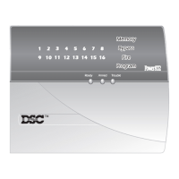
The two sets of attributes (1-8 and 9-16) can be toggled by
pressing ‘9’ within any zone’s attribute section. If the
Ready LED is on, the keypad is indicating Zone
Attributes 1-8; if the Ready and Armed LED’s are on, the
keypad is indicating Zone Attributes 9-16. The following
options can be enabled or disabled by zone.
NOTE:
DO NOT change Fire zones attributes from the default settings.
[165] - Maximum Dialing Attempts To Each Phone
Number
This value represents the number of attempts that will be
made to each telephone number when communicating.
The default value is 007 attempts. Valid entries are 001-015.
NOTE:
The PC5010 CP-01 will not allow more than 15 dial-
ing attempts to a single phone number. If a value higher
than 15 is programmed in Section [165], the panel will still
only make15 attempts.
[166] - Post-Dial Wait For Handshake
This value represents the time the communicator waits
for a valid initial handshake from the receiver after dial-
ing the programmed telephone number. The default
value is 040 seconds.
[167] - T-Link Interface Communications Wait for
Acknowledge
This value represents the time the communicator waits
for an ACK from the receiver after sending a SIA Packet.
The default is 020 seconds.
[170]-[178] Timers
[170] - PGM Output Timer
This value represents the period of time (in seconds) that a
PGM will activate if programmed to follow the PGM
Timer.
The default value is 005 seconds. Valid entries are 001-255.
NOTE:
This option does not affect outputs programmed as
Sensor Reset (Type 03).
NOTE:
If a System Event PGM is programmed to follow the
Command Output Timer, all attributes must be enabled.
[175] - Auto-arm Postpone Timer
This feature controls the sequence of events after a valid
access code is entered during the Auto-arm Pre-alert. If
the Auto-arm Postpone Timer is programmed as 000, the
Auto-arm will be cancelled. If a value between 001 and
255 is programmed, then the Auto-arm will be postponed
for the corresponding number of minutes and the panel
will resume normal operation. The panel will also log the
appropriate user log for the access code which postponed
the arming. When the postpone time expires, the panel
Auto-arm Pre-alert will be re-initiated (unless the parti-
tion is armed). The Auto-arm can be postponed multiple
[101]-[132] ZONE ATTRIBUTES
Option Attribute On/Off Description
1BellON
An alarm will cause the bell output to activate.
OFF Silent Alarm
2 Bell Type ON
The bell output will be steady when the zone is in alarm.
OFF
The bell output will pulse when the zone is in alarm.
3 Chime ON
Every keypad will chime when the zone is violated and when the zone is secured. Door Chime
will work in both the armed and disarmed states.
OFF
The zone will not chime the keypads.
4BypassON
The zone can be manually bypassed.
OFF
The zone cannot be bypassed.
5 Force Arming ON
The system (partition) can be armed with the zone violated. The zone will be temporarily
bypassed, and when the zone is secured it will be added back into the system.
OFF
The system cannot be armed if this zone is open.
6 Swinger Shutdown ON
The zone will shut down after a programmed number of alarms, inhibiting further transmissions
to the monitoring station. The bell can follow swinger shutdown if programmed.
OFF Swinger Shutdown Disabled
7 Transmission Delay ON
The reporting of zone alarms will be delayed for the programmed time. If a valid access code is
entered within this time, no alarm signal will be communicated.
OFF
When an alarm occurs, the reporting code is transmitted immediately.
NOTE: Transmission Delay cannot be used on fire zones.
8 Wireless ON Zone is Wireless.
The zone will ignore the main board zone (if applicable) and respond to the
corresponding zone enrolled on the PC5132.
OFF Zone is Hardwired.
The zone uses the corresponding hardwired zone.
9 Cross Zone ON Zone is a Cross Zone
. Zone is enabled for Cross Zoning.
OFF Zone is not a Cross Zone.
Zone is not enabled for Cross Zoning. The default state for the Cross
Zone attribute is OFF for all zone types.
NOTE: DO NOT change Fire Zones attributes from the default settings.
WWW.DIYALARMFORUM.COM

 Loading...


