2
1.1 Installation:
1
Select desired Location and Mounting Option
1
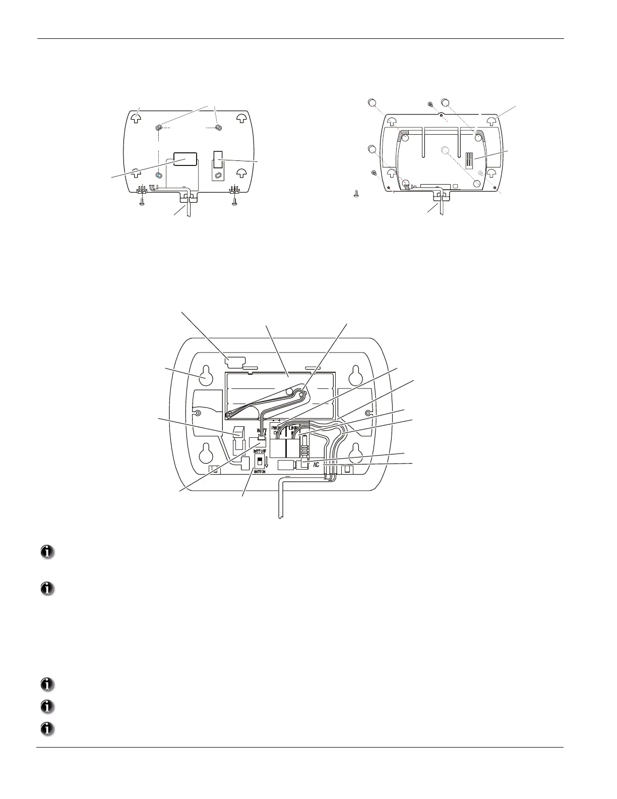
Wall Mount Installation
(a) Drill 4 holes in the desired location and insert drywall plugs.
(b) Route wiring through the access hole or cable guide as required.
(c) Secure backplate to wall using the 4 screws provided.
Desk Mount Installation
(a) Remove adhesive backing and install the rubber feet (4).
(b) Route wiring through the cable guide.
2
Connect wiring to the terminals indicated. See Section 1.2 Wiring for details.
Figure 1, Wiring Details
Do NOT apply power until wiring is completed.
3
Connect battery cable connector to the PC Board.
Ensure connector is oriented correctly.
4.
5.
6.
7.
8.
9.
Position Alarm System mounting holes over mounting hooks. Slide unit downward until unit snaps in place.
Secure Alarm System to wall or desk mount with the two screws provided.
Enroll devices. Enter [][8][Installer Code][898]. See Section 2, Wireless Device Enrollment.
If performing Template programming, enter [][8][Installer Code][899]. See Section 3, Template Programming.
Enter Advanced Programming if required. See Section 6, Advanced Programming.
Test System by violating zones and verifying successful transmission to the monitoring station.
See DLS Programming on page 9 for reprogramming an existing Installation.
AC Power must be present for the Alarm system to answer incoming calls from DLS.
After the initial installation 24 Hrs. is required to fully charge the standby battery.
2.5" (63 mm)
Route cables via
access hole or cable guide
as required
Ensure tamper switch
makes secure contact
with mounting surface
3" (76 mm)
Mounting Holes (4)
Rubber Feet (4)
Cover Screws (3)
Cable guide
Tamper switch
contact surface
Tamper
Switch
Battery Switch
16.5Vac Connector
wiring channel guide
wiring channel guide
Phone Line In
wiring channel guide
Battery
Connector
Battery (Ni MH)
7.2V , 1500 maHr
DC
Mounting Holes (4)
(mates with mounting hooks
on Wall or Desk mount backplate.
PC Link Header
Battery Cable
Channel Guide & Clip
 Loading...