Signal Connection to External Devices
▲
■■■■■■■■■■■■■■■■■■■■■■■■■■■■■■■■■■■■■■■■■■■■■■■■■■■■■■■■■■■■■■■■■■■■■■■■■■■
DS1104 Hardware Installation and Configuration March 2004
I■■■■■■■■■■■■■
▼
134
■■■■■■■■■■■■■■■▼
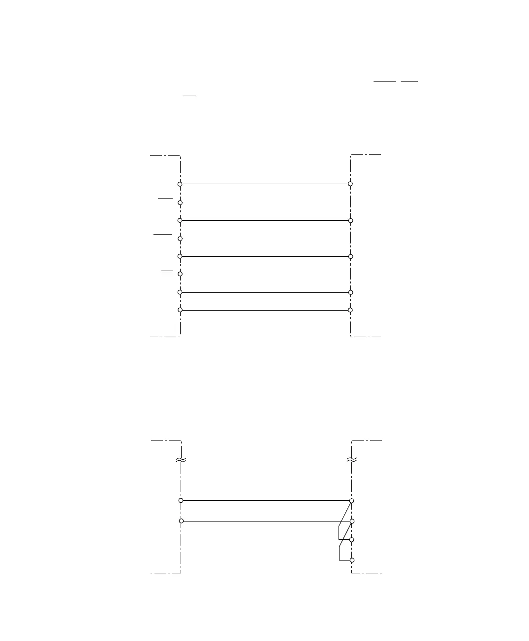
Encoder providing
single-ended TTL mode
If the single ended TTL mode is used, the inverted pins PHI90, PHI0
and IDX
must be left unconnected (see below).
Encoder providing
SENSE lines
If your encoder has sense lines, connect SENSE+ to Vsupply and
SENSE– to GND. Connect the sense lines directly within the connector
of the encoder (see below).
GND
Incremental encoder
output
DS1104
GND
PHI0 PHI0
PHI90
IDXIDX
PHI90
VSupply
VCC
PHI0
PHI90
IDX
Incremental encoder
output
DS1104
GND
VSupply
SENSE +
SENSE -
GND
VCC