Signal Connection to External Devices
▲
■■■■■■■■■■■■■■■■■■■■■■■■■■■■■■■■■■■■■■■■■■■■■■■■■■■■■■■■■■■■■■■■■■■■■■■■■■■
DS1104 Hardware Installation and Configuration March 2004
I■■■■■■■■■■■■■
▼
140
■■■■■■■■■■■■■■■▼
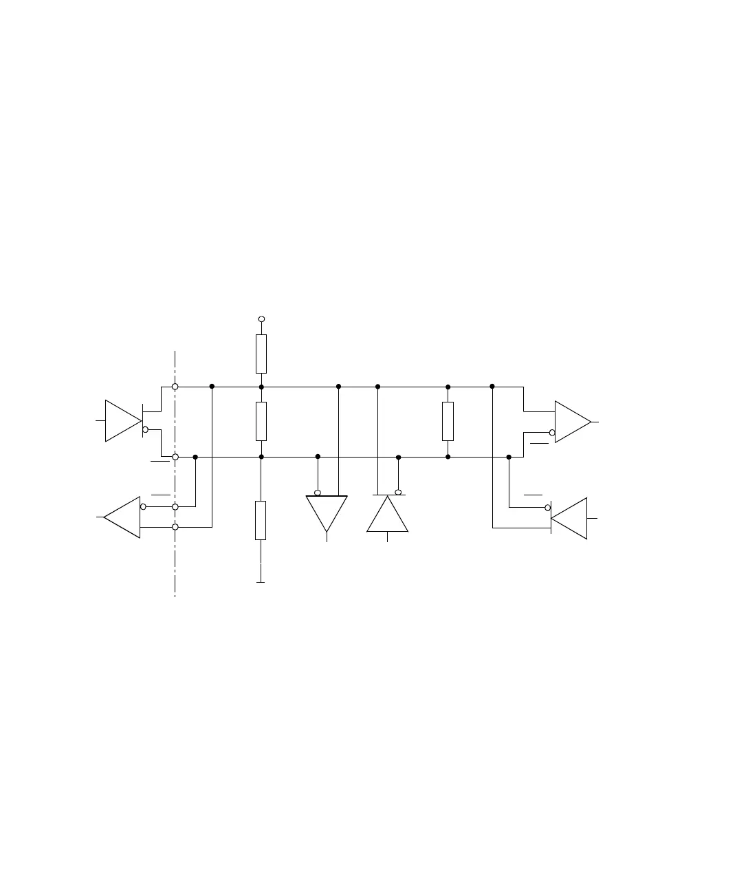
The figure below shows a typical 485-compliant network, with a
transceiver at both ends of the cable and transmitters/receivers placed
along the length of the cable. Since each device communicates
bidirectionally, it is impossible to determine where the transmitter is
and to which device the transmitter is currently transmitting at the
moment. Moreover, it is also possible for the transmitter to be in the
middle of the line. So, both ends of the line have to be terminated
with a terminator.
The termination resistor Z
T
, must be within 20 % of the characteristic
impedance of the cable (Z
0
) and can vary from 90 Ω to 120 Ω.
Avoiding undefined
conditions (RS485)
If no transmitter is currently active in an RS485 network, undefined
conditions may occur. To avoid these conditions, you must provide a
pull-up and a pull-down resistor (each 1 kΩ) as shown above.
TXD
RXD
TXD
RXD
DS1104
(RS485 mode)
Z
T
Z
T
T = Transmitter
R = Receiver
T
R
R
T
R
T
TXD
RXD
1 k
Ω
1 k
Ω
+5
V
Pull-up
resistor
Pull-down
resistor
RXD
TXD