■■■■■■■■■■■■■■■■■■■■■■■■■■■■■■■■■■■■■■■■■■■■■■■■■■■■■■■■■■■■■■■■■■■■■■■■■■■■■■■■■■■■■■■■■■
▼
Connector Pinouts and LEDs
DS1104 Hardware Installation and Configuration March 2004
89
▲
■■■■■■■■■■I
▲■■■■■■■■■■■■■■■
C
WARNING! Hazardous voltages.
Risk of electric shock and/or damage to the hardware.
■ Do not connect any high-voltage devices to the I/O connectors of
the panel.
N
For the CP1104 and CLP1104 Connector Panels, the total load of all
connector pins that provide access to the PC power supply must not
exceed 500 mA (CP1104) or 400 mA (CLP1104).
The VCC lines are protected against short circuits by a common
multifuse on the DS1104.
CP1
CP2
CP3
CP4
CP5
CP6
CP7
CP8
CP9
CP10
CP11
CP12
CP13
CP14
CP15
CP16
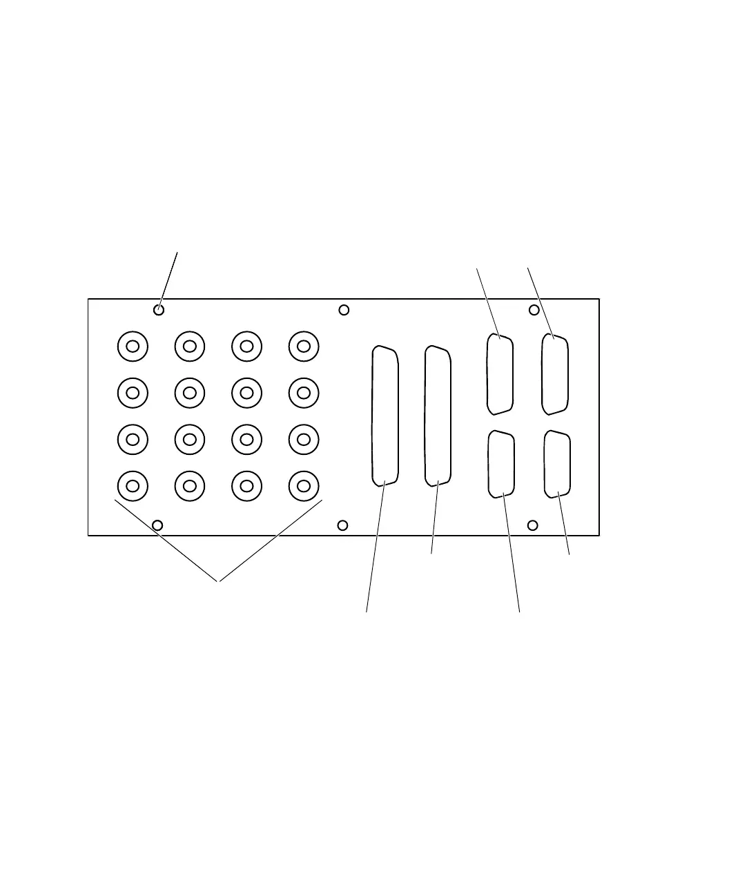
Hole for 19'' rack mount
Incremental Encoder Interface connectors
UART RS232 connector
(CP21)
UART RS485/RS422
connector (CP22)
Slave I/O PWM
connector (CP18)
Digital I/O connector
(CP17)
BNC connectors
(CP1 ... CP16)
(CP19)
(CP20)