HV-500 TECHNICAL DESCRIPTION (BETA VERSION)
2
Revision 1.31
CONTENTS
Overview ......................................................................................................................................................... 3
History ......................................................................................................................................................... 3
Related documents ..................................................................................................................................... 3
Liability and safe use of this unit ..................................................................................................................... 4
Main features .................................................................................................................................................. 5
Specifications................................................................................................................................................... 5
Current limit reduction .................................................................................................................................... 6
Power loss ....................................................................................................................................................... 6
Efficiency ......................................................................................................................................................... 7
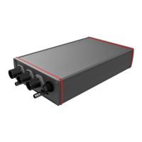
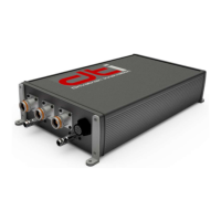
physical description ......................................................................................................................................... 8
Mounting options ........................................................................................................................................ 9
Connections ................................................................................................................................................... 10
Harness connector pinout (H) ................................................................................................................... 10
Motor sensor connector pinout (M) ......................................................................................................... 11
Incremental encoder + SSI ..................................................................................................................... 11
Hall sensors ........................................................................................................................................... 12
High power connection ............................................................................................................................. 12
Liquid cooling connection ......................................................................................................................... 12
PC connection and control ............................................................................................................................ 13
Wiring ............................................................................................................................................................ 13
Harness connector wiring.......................................................................................................................... 14
Input supply ........................................................................................................................................... 15
Analog input .......................................................................................................................................... 15
Digital input ........................................................................................................................................... 15
Digital output......................................................................................................................................... 15
CAN periphery ....................................................................................................................................... 15
RS 232 pheriphery ................................................................................................................................. 16
Motor sensor connector wiring ................................................................................................................. 16
Encoder ................................................................................................................................................. 16
Hall sensor ............................................................................................................................................. 17
High voltage wiring .................................................................................................................................... 18
 Loading...