Dear music lover,
Please read through these instructions
care-
fully before
you
operate
your
new automatic
turntable for the first
time. By doing
so,
you
will avoid
possible
malfunction because of
incorrect
connections or improper operation.
Unpacking
and setup
These instructions
apply
only it
you
have
pur-
chased
the turntable
as a separate component.
Begin by
unpacking
the
base and
putting
it
it the
place you
have
selected
for
the
player.
lf
you plan
to install
the
player
in
a
custom
cabinet or an existing
piece
of
furniture
without
using
its
special base, the
necessary
cutout
must
be
made according to the tem-
plate
f
urnished
with the turntable.
When
you
unpack
the
automatic turntable,
set aside
the
styrofoam
container with the
turntable
platter
and all the accessories. Now
install the
turntable chassis
on
the base
as
f ollows.
First
feed
the
power
cord and audio cable
through the top of the
base, then
out through
the
openings
in
the
bottom
of
the base.
Then
press
the
left rear transport
safety screw
to
the
side, and
set the
player
chassis
into
the
base,
rear
edge first, so
that both
rear
spring
cups
fit
into
the appropriate
holes in the
base.
Move
the other two transport
safety screws
inward
in
a similar fashion, and settle
the
left
and right
front
spring cups
into
their
holes. Then turn the transport safety screws
clockwise
until
they are tight. The chassis
is
now spring-mounted.
After
installing
the
chassis
in
the base,
lower
the turntable
platter
slowly
and carefully
onto its shaft. As
you
set the
platter
onto
the
shaft, an
oil-soaked felt
washer will be
pushed
out o{ the
platter
bearing,
thus
oiling
the bearing. Discard the
felt
washer. Secure
the
platter
to
the shaft with the spring ring,
according to
Fig. 25
B.
lnstall the
tonearm
counterweight
at the
rear
of
the tonearm and balance
the tonearm..For
instructions,
rdad
Balancing the Tonearm on
page
'10.
lnstructions for
setting
stylus
force
and anti-skating compensation
are
described
on
page
l 1.
Caution.
After
initial
installation,
or after
being
moved,
the
player
should be
run once
through its
cycle
with the
tonearm locked
on
its
rest
(push
operating
switch to
"start"
and
rotate
platter
by
hand until switch
returns to
its
neutral
position.)
8
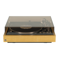
ln diesem Fall stellen Sie die
Drehtaste für die
Plattengrößeneinstellung auf 30
cm,
bzw.
12":
Neben
der
Tonarmstütze wird
die
Re-
gul
ierschraube
@
sichtbar.
Dann legen Sie eine 3o-cm-Platte auf und
starten das Gerät.
Wenn
der Abtaststift
zu
weit innen auf der Schallplatte aufsetzt,
drehen Sie
die
Einstellschraube
wenig
nach
links;
wenn er zu weit außen
aufsetzt nach
rechts.
Future
transport
To
prevent
damage to the
player
during
transport, we strongly
recommend removing
the
platter
and carrying
it
separately. ln
addition, turn the transport
safety screws
counterclockwise
(upward)
as
far
as
they
will
go,
until the chassis is held
f
irmly
against the
base.
(Fig.
1C).
4F tr +-
\g F i+:
--TEi*
Aö
Fli lJ t'
''
r
+-
€'F€
ABC
Fig.
1
Connection to
power
line
For units
already
installed
in concole
or
com-
pact
systems,
consult the
instructions
for the
system.
Service
Alle Schmierstellen sind ausreichend
mit Öl
versorgt.
Damit wird unter normalen Betriebs-
bedingungen
lhr Gerät
jahrelang
einwandfrei
funktionieren. Versuchen
Sie an keiner
Stelle
selbst
nachzuölen. Es
müssen Spezialöle ver-
wendet werden. Sollte lhr
HiFi-Automatik-
spieler
jemals
eine
Wartung
brauchen, bringen
Sie
ihn bitte entweder zu lhrem Fachhändler
oder
fragen
Sie diesen nach
der
Adresse
der
nächsten autorisierten
Dual Kundendienst-
werkstatt. Bitte achten
Sie darauf
,
daß immer
Original-Dual-Ersatzteile
verwendet
werden,
Versenden
Sie lhr Gerät nur
in
der Original-
Verpack u ng.
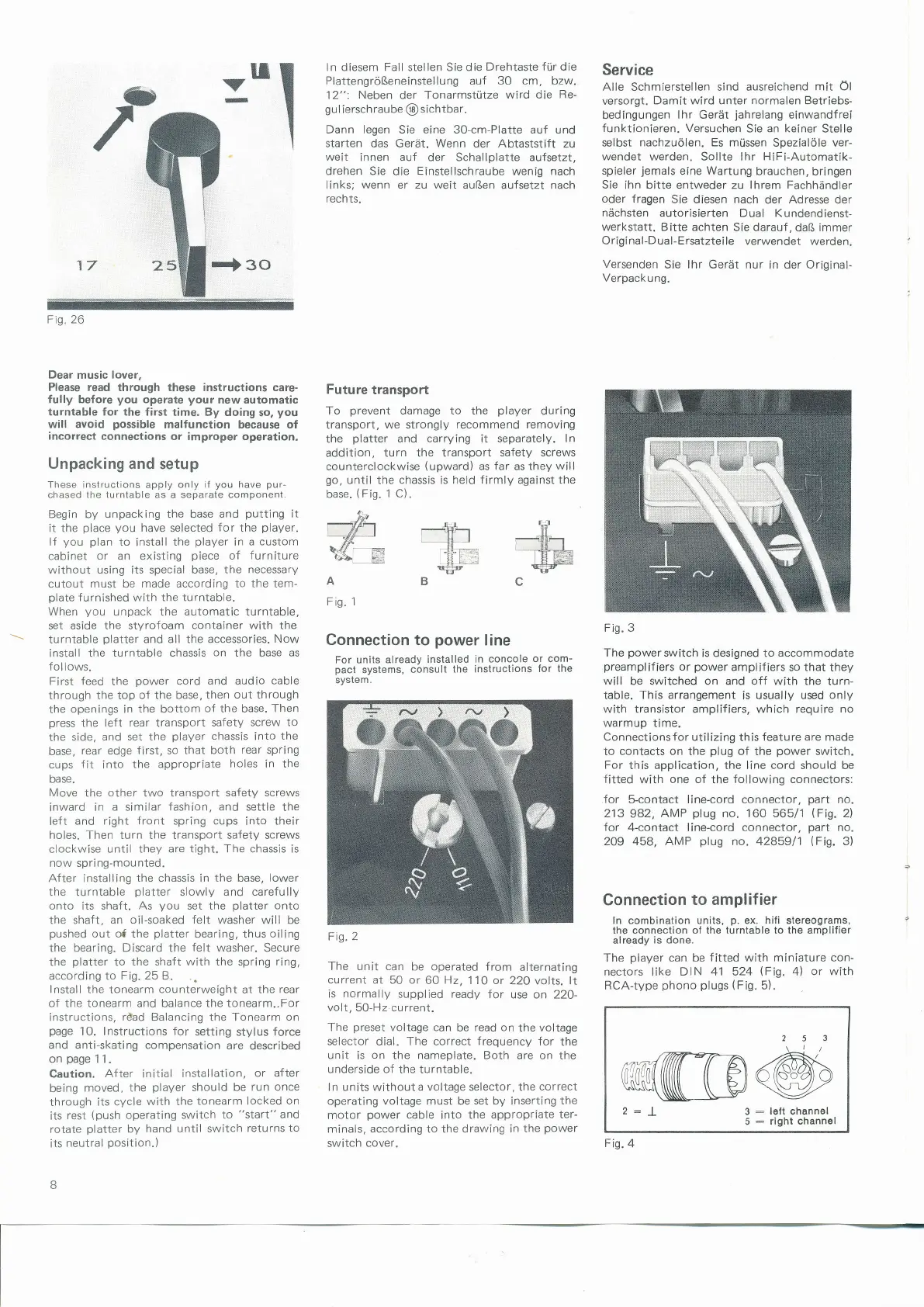
Fig.3
The
power
switch
is designed to
accommodate
preamplif
iers
or
power
amplifiers
so that they
will be switched on and off with the
turn-
table.
This arrangement
is
usually used
only
with
transistor amplifiers,
which
require no
warmup time.
Connections for
utilizing this
feature are made
to
contacts on
the
plug
of
the
power
switch.
For this application, the line cord should be
fitted
with
one of
the
following connectors:
for
5-contact line-cord connector,
part
nö.
213
982,
AMP
plug
no. 160 565/1
lFis.
2l
for
4-contact line-cord
connector,
part
no.
2Og 458, AMP
plug
no. 4285911
(Fig.
3)
Connection
to ampl if ier
ln
combination
units,
p.
ex. hili stereograms,
the connection ol the turntable to the amplifier
already
is
done.
The
player
can be
fitted with
miniature
con-
nectors
like
DIN 41 524
lFig.
4)
or with
RCA-type
phono plugs
(Fig.
5).
253
\l/
2:I
3:lottchannel
5
:
right channel
Fig.
4
u
v
Fig.2
The unit can
be operated
from
alternating
current
at 50 or
60
Hz,
11O or
220 volts. lt
is
normally
supplied ready for
use on 22O-
volt,50-Hz-current.
The
preset
voltage can
be read
on
the
voltage
selector
dial. The correct
frequency
for
the
unit
is
on
the nameplate. Both
are on the
underside of
the turntable.
ln units without
a voltage selector, the
correct
operating vottage must be
set
by inserting
the
motor
power
cable
into
the appropriate
ter-
minals,
according
to the
drawing in the
power
switch
cover.
Fig" 26
 Loading...