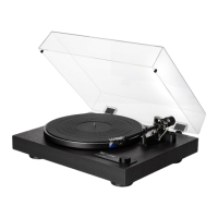
Function description
CS 607
Motor control
The
Generator
G
supplied the motor control with a strickly speed
pro-
portional
frequency, which is feed from
disturbing
harmonics by
C
9001.
The frequency is then routed via R 9001 to the comparator lC
9001,
which
functions as a
Schmitt-trigger with R
9002.
The
pulses
at
pin
7
(lC
9001)
are differentjated
with
R
9004,
C
9002 and R
9006 and
routed through transistor T
9001 for a short
period.
This also causes
the capacitor C
9003
to
discharge. The resistors
B
9008
to R
901 1
determine
the speed
at
which C
9003 ls charged whereby the
selected
speed. A sowtooth
voltage is then routed to
pin
2
(lC
9001)which is
compared to the medium
voltage formed by R
9012 and
R
9020.
The
signal from the output
(pin
1
,
lC
90O1
)
is
routed
via D 9O02 through
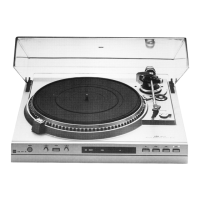
Functional
description
CS 617 O
Motor control
The
generator
G
supplies the
motor control
with a speed-pro-
portional
frequency which is
cleared of disturbing
harmonics
by C 901 1
and is routed to
transistor
T
9005
via C 901
2. Tran-
sistor
T
9005
amplif ies
the voltage
by a
factor
of 18O.
lC I 9005
which
functions as an operational
amplif ier
receives its working
point
from the
voltage
distributors
R
9019
and C
9013.
The
positive
feedback through
R
9020
accelerates the switchover
process
of the operational
amplifier
in
the
pulse
of the
generator
frequency resulting in steep
flanked
pulses
at
pin
7
which
control
the
phase
comparison circu;t
I
9003
via
T
9002.
The differenti-
ated
pulses
through
C
9O14,
R
9021
and
R
9022
briefly control
T
9006, resulting
in
the capacitor C 901 5
discharging
via R
9026.
Depending on
the selected speed
the
capacitor C 901
5
is
charged
in
the direction
of
earth
through
R
9024,
R 9025,
R
9027
and
R
9028.
At the speed
of 33 only
R
9027
and
R
9028
are
effec-
tive. At the speed
of 45
T
9007
becomes
conductive so
that the
resistors
R
9024
and R 9025
are also included in
the
circuit.
Therefore,
when
carrying out a speed comparison
the speed
33
should
always be
adjusted before the speed
45.
The
sawtooth-
shaped
voltage
at
pin
2 of
I
9005 is
compared to
the medium
voltage
formed by R
9029
and R
9O40.
lf the
voltage falls short
of
the medium
voltage
a
positive
output
pulse
appears at
pin
1
at I
9005.
This
pulse
reaches
T
9008
via the differentiating
circuit
R
9031
,
C 901
7 and R 9032 whereby
C 901 8
discharges to the
O.7 V
produöed
by the voltage distributor
R
9034,
R
9035.
Depending
upon
pulse
duration C 9018
is recharged
Through
D
9007,
D 9008
and
R
9033,
R
9036.
This
reaches
the
filter
circuit
R
9037,
C 9019
wnich
controls T 9009
which acts
as a
Darlington
circuit
and
therefore
also controls the
motor voltage.
Ouartz
circuit
The
quartz
crystal oscillator
consisting of
T
90O1,
R
900 1,
R
9002,
C 9001
.
.
.
C
9003 and the
direct wave
quartz
crystal
with
4608
MHz,
reaches
via
pin
9 the distributor
I
9001
which
can be
programmed.
lf
thespeed
switchoverS
2switch
is
in
the
"33"
position
then the input
data of the inputs
P1
up
to
Pg
have the
following bit
pattern:
H
L
H L
H
L H
H.
This correspondstoa
decimal
figure of 135
where the
values
of
Pi
-
Pg
correspond to
the numbers 1,2,4,8,1O,20,40,80.
ln
position
"45"
the deci-
mal figure 1oO
is
represented
by the
bit
pattern
(P1
-
Pg)
L L L
L L H L
H.
ln thiscase the
frequencies34.13
kHz
or46.08
kHz
appear at the output
pin
15 of
I
9001
(O
8).
These frequencies
are
divided bv
512
l29l
by I
9OO2
whereby the
working f
requen-
cies of 66
213
Hz
or 90
Hz
or 90
Hz
are
produced
(pin
12). The
the
filter C 9004, R 9O18,
R
9017, C 9005, R
9005
and controls the
transistors T
9002 and
T 9003
functioning
in the Darlington
circuit,
which immediately
feeds the motor.
The
voltage drop at R 90i9 is
proportional
to the motor
current and
controls the
medium voltage at
pin
3
of lC
9001. This compensates
for
a drop in speed which
depends on torque.
When
the motor is started,
this
effect
is neutralized by R
902'1 and
D 9003.
Pitch
With the
potentlometer
PITCH and the resistor
R
9014,
the medium
voltaqe
at
pin
3
(
IC
9001
)
can be adjusted.
output
reaches
the
phase
comparison
circuit
which
is
formed
from the two
D
-
flip-flops
19003, R
90iO and
D 9O01.
The
reference
frequency
which corresponds
to the
first
speed
is ob-
tained
from I
9005/pin
7 which
is
connected
to an inverter
by
T
9002,
R
9005,
R
9006
and
R
90O7.
The two
outputs of the
phase
comparator
circuit
contain the
data of the
phase
angle
from
-3600
up to
+3600
in
the
form
of
differing
pulsewidths.
These
signals
are decoupled by the diodes
D
9002 and
D
9003
and are adapted to suit the
control circuitry by the resistors
R
901
1,
R
9012
in
such a
way that a
synchronous speed
is
maintained within a tolerance oI
!
3
%. The
synchronization is
achieved by a
positive
current from R
9011
flowing
into
the
speed
governoring
capacitor
C
9015
when the
phase
angle
is
leading.
This
slightly lowers the sawtooth
voltages
(measured
from
+12
V)
resulting in
a
lowering
of the motor speed.
lf
the
phase
angle is lagging
a negative current via
R
9O12
flows
into
the capacitor
C
9O1
5
resulting in an increase
of the motor speed.
-
This
therefore ensures
that
the
correct
speed is
maintained.
Pitch
The voltage drop at
R
9039
ls
proportional
to the motor
current
and
controls
the
medium voltage
at
pin
3
of
lc
9005 via
R
9o4o
compensating the drop in speed
which depends
on the torque.
lf,
f or example, transistor
T
9O1O is strongly
f
orward
biased
(Vc
5.3
V)
the effect is
neutralized through
D
9009
and
R
9041.
For
pitch
adjustment,
the medium voltage
at
pin
3 of
I
9005
can
be slightly shifted
to
+
or
-
by the
potentiometer
R
9042
through
R
9030.
ln
this
way
the speed adjustment
lies
in
the range!5''/o.
This adjustment is
only
possible
in
the
position
"pitch"
and in
quartz
mode. This
is
stored
by
a
quartzlpitch
Switch
S 2.
Stroboscope
The exact
pulses
for
the stroboscope
are
obtained
as
follows:
The
frequency of the distributor
I
9002 is
differentiated
by
R
9009,
C
9008
and
R
9013
and
reaches
the base of
T
9003
through the
diode D
9004.
This
is
transferred for a short
period
in
a
reversed
biased state whereby a
current
is
set up at the base
of T 9004 resulting in
a O.7 V lower voltage
at R
9016
than at
the base. The
constant base voltage also
ensures a
pulse
voltage
through
the LED's D 9005
and
D 9O06.
The light duration
mainly depends
on C
9O08
and
R
901
3.
The flashing frequency
at 33 rpm is 66
213 Hz and at 45 rpm 90
Hz; each
value
has
the
precision
of a
quartz
crystal.
-
12
 Loading...