Mechanical
Part
General
The following item numbers refer to the spare
part
lists and
exploded
drawings.
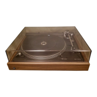
The
cover
can simply be removed by the
hinged
clips.
Base
The base 57 is secured by
four
cheesehead self-tapping
screws
(base
set
55) and with two screws
20
on
the spring
cluster.
Front
scre€n
The front screen
63 is secured to the casing 95 by two hexagonal nuts
120.
Removing the cüassis comdet6
It
isrecommended to
followthe
following
instructions when dismantling
the chassis complete:
1) Remove cover
95 and turntable 92. Remove the base 57.
2)
Loosen the three
cheesehead
screws 93. Lift cover
94
and turn
so
that
it
can be removed
over the tonearm bearing
and tonearm.
3) Swing
in
tonearm
135 and solder
connecting
leads. Hold chassis.
4) Remove
the
four
cheesehead
screws 19 of
the spring cluster 17
and
remove
chassis from
the
casing
95.
Tonearm and
tonearm bearings
Dismanting tonearm
complete
with
tonearm
bearings
It
is
recommended to
follow
the
following order:
1) Set the
control knob 129 in
the
zero
position.
Lock
the
tonearm
135. Loosen
the tensioning screw 132 and remove the
weight
166.
2)
Remove the
cheesehead screw
84,the
hex nut
83 and cover
plate
82.
Unsolder
the tonearm leads
at
the shortout 77.
3) Remove the machine screw 181
,
the micro switch and the switch
support
176.
4) Remove
lock
washer
155. Lift off
main
lever 154
and
bearing
sup-
port
153.
5) Remove
the
hex nut
1 1O and the sunk screw 1 13 and counter bearing
112.
6)
Hold tonearm.
Bemove the machine screw
73
and
lift Tonearm
cpl
.
Reverse
thi s
procedure
when reassebli ng. Please bea
r in
mind
the threshold
pins
is correctly
positioned
in the ball bearings.
Removing
the tonearm
from the
bearing case
l) Remove weight
166. Screw
out
tensioning screw 132 and set the
control knob
129 in the zero
position.
2) Remove cheesehead screw
84 and
cover
plate
82.
Unsolder
the
tone-
arm
leads at the shortout 77.
3) Loosen the countersunk
screw 130. Remove control knob
129
washer 128 and
pointer
127.
4)
Loosen
lock
nut
98 and remove setscrew
99.
5) Remove
tonearm
135.
Assembly should be carried out
in
the
reverse order.
Changing
the
spring
casing
Remove
the
tonearm
135
from
its bea
rings
1
26
fol
I owi
ng
the
i
nstruct
ions
described
above.
Fiemove
the spring case 133.
Special attention must be
paid
to ensure that the coil spring fits
in the
recess of
the
bearing
134-
Reassemble the tonearm. Adjust the bearing
play
as described below.
Adiustment
of tonearm bearings
The
tonearm must be
exactly
balanced.
Both bearings
should have
very
little
or no
play.
The
horizontal tonearm bearing
is
correctly
adjusted
when
the tonearm
can
freely slide in
and
out with the antiskating adjust-
ment set to
"0.5"
The vertical tonearm bearing
is
correctly adjusted
when the tonearm
freely
swings back into
position
after
being tapped.
The
play
in the
horizontal
tonearm bearing can be adjusted
with the
setscrew 99 and the
counter nut
98.
The
play
in
the
vertical tonearm
bearing can
be adjusted with the setscrew 1 18 and the counter nut
1 19.
Shortout
Adjustment
point
When
the curve
wheel
is in the zero
position
the contact distance
between
the contact spring F and
shortout contact L should be
0.5 mm.
lf
necessary,
bend shortout contact slightly and clean the contact spring
with
a suitable
cleaning
agent.
Tonearm lift
Adjustrnent
point
The tonearm
lift
height
can be adjusted
by means
of the
adjustment
screw and
should be
between ca.
5 mm.
Changing
the
lift
board
1) Lock tonearm 135 in
position.
Remove
the
screw 181,
the micro-
switch
34 and
the
switch
support 176. Remove the
lock
washer
155.
Lift off main lever 154 with bearing
support 153.
2) Remove
the
lock
washer
180 and the cam wheel
17-9.
Loosen
the
machine
screw 1O8. Remove
the slide bush
171,lift the adjusting
bar
17O and
remove the lift board
105.
Assembly
is
carried
out
in
the
reverse order.
Adiustment
points
Set
down
point
The
set down
point
of the tonearm
can
be
altered with
the ecentric bolt
E
(Adjusting
plate
71). The setting is
effective not
only for
17
cm but
also
for
30 cm records.
Shut-off
point
The shut-off
point
can be
varied
within
the shut-off range
(record
dia.
i16 to 122 mm) .
Remove
platter
92.
Using
a screwdriver adjust shutoff rail 150 through
the hole
in
cam wheel 30.
Fuses
After
removing the turntable 92
the cover of the
fuse
switch 27
can be
removed allowing access to the fuse
28.
16
 Loading...