06
Dualtron Thunder User Manual Dualtron Thunder User Manual
07
instrument panel
Throttle
Main Control Unit 2
DC-DC
Converter
Break Unit
Left
Break Unit
Right
LIGHT
SWITCH
Motor
Rear
Green
Yellow
Blue
Green
Yellow
Blue
Red
12V
Red
Red
Red
Red
Red
Red
Red
Red
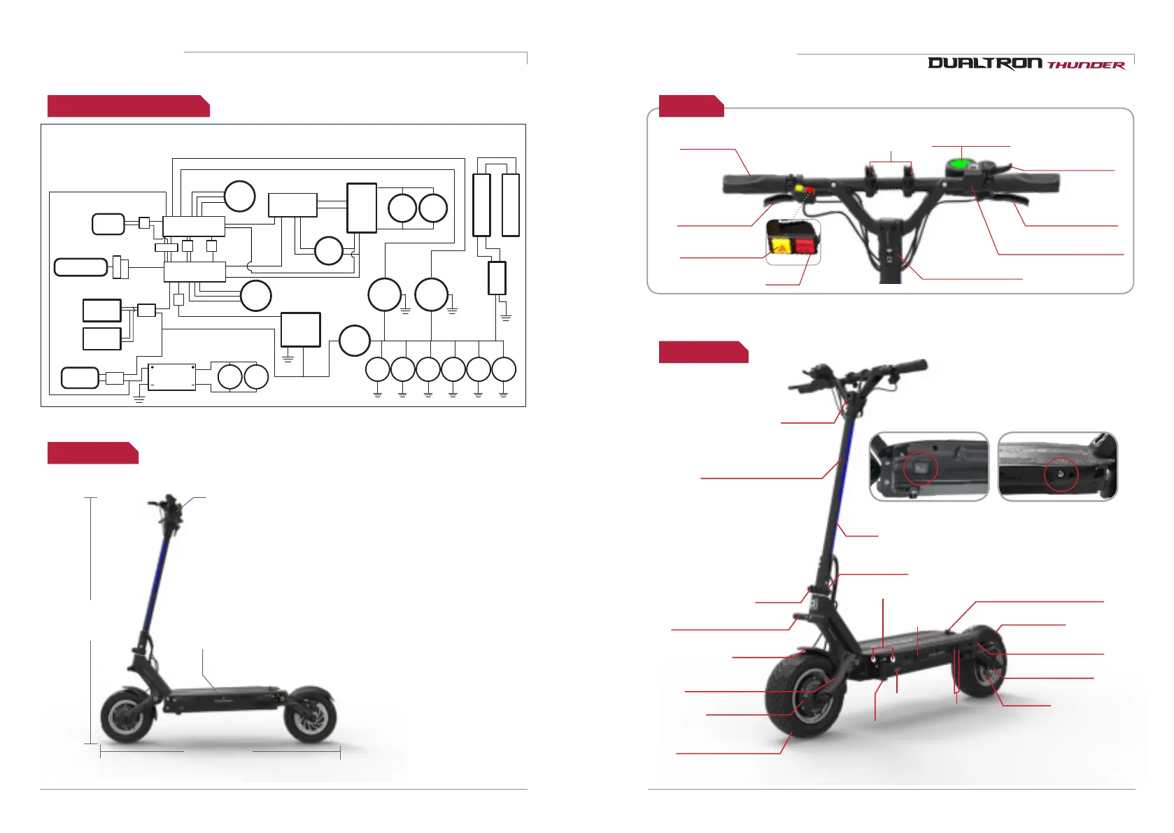
DUALTRON THUNDER WIRING DIAGRAM
Emergency
Light Switch
7P Con
6P Con
3P Con
2P
Con
2P
Con
2P
Con
2P
Con
2P
Con
Black
White (N/C)
White (1P)
Green
Green Green
Yellow
Black
Black
Black
White
White White
SIDE LED LIGHT1
SIDE LED LIGHT2
60V
Battery
Main Control Unit 1
Charge
Socket
1
Charge
Socket
2
Sub
Battery
Socket
BRAKE
LIGHT 1
BRAKE
LIGHT 2
LIGHT 2
BLUE
LIGHT1
BLUE
LIGHT2
LIGHT 1
Yellow
LIGHT L
Yellow
LIGHT R
LIGHT 4LIGHT 3
2P
Con
U IN LED OUT
LED Controller
STEM
LED MOUDEL
Single / Dual
Switch
Blue
Main Switch
Motor
Front
Body frame
Electric wiring diagram
Product size
Handle
1219mm
1238 x 543 x 319mm
( Length(L) x Height(H) x Width(W) )
Fingerprint recognizer(Option)
* Errors may occur depending on the measurement method.
1137mm
Handle width
609mm
Footrest width319mm
Unfolded
Folded
handle folding fixing part
EYE throttle LCD
instrument panel
Index finder
throttle(Accellerator)
Handle grip
Brake lever
(+Electronic brake)
Handlebar fixing
QR lever
Brake lever
(+Electronic brake)
Motor system
selection button
Emergency button
Handle stem
Main power
switch
Bottom
mood lamp
Rear suspension
Rear fender
Handle folding locking part
QR lever
Rear light(Brake light)
Charging port
Front lamp
locking slide
Handle post(Steering tube)
LED bar
Main power switch
LED lamp button
Front suspension
Front fender
Front&Rear 10” wide
tubeless tire
Front motor
Rear motor
Auxiliary battery
connecting port
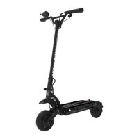
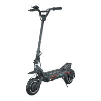
Name of each partProduct structure
Light mount bar(Option)