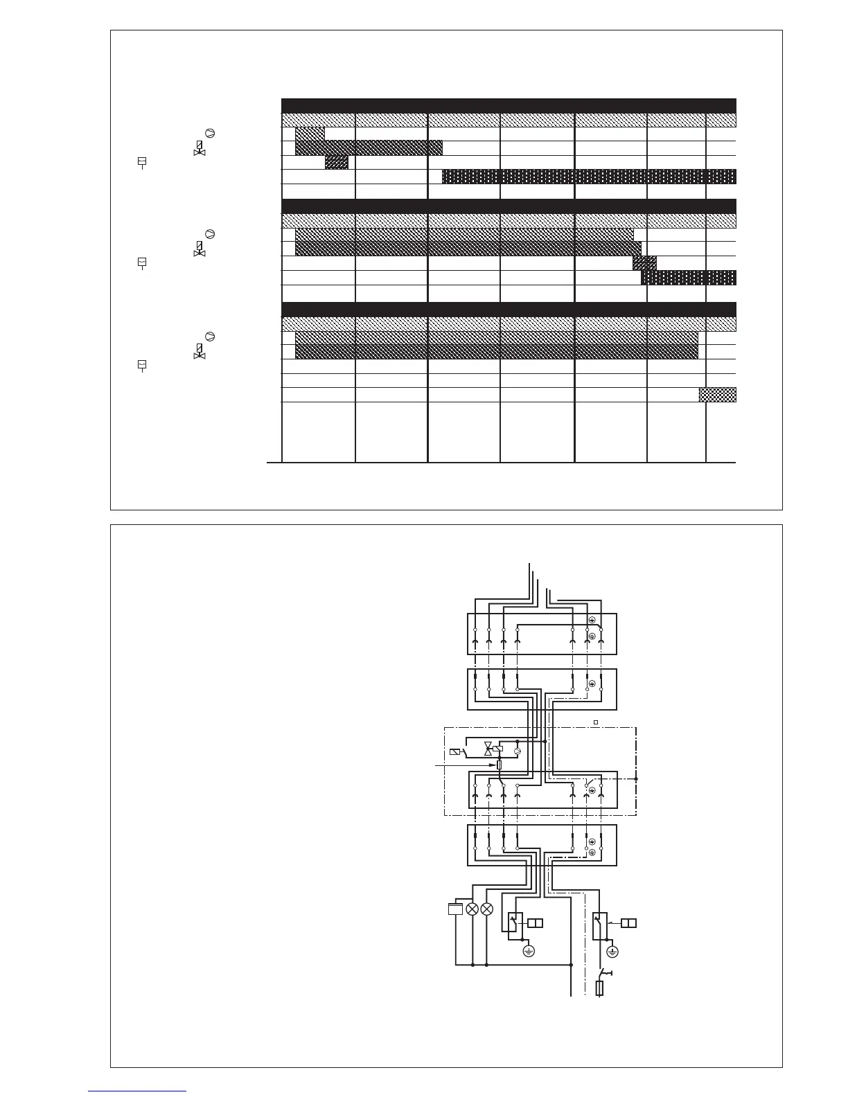
5 … 12
Electrical connection
VPS 504 S01
The VPS 504 S01 is connected in
series between temperature regula-
tor and automatic burner control via
a 7-pole connector. Connector pin
assignment between burner and boiler
is performed as per DIN 4791. For
pin assignment, refer to connection
diagram.
If the heat generator is wired as per
DIN 4791, no boiler- or burner-side
rewiring is necessary for electrical
connection.
The burner female connector is con-
nected with the cable-to-cable male
connector of VPS 504 S01.
The female connector VPS 504 S01
is connected with the cable-to-cable
male connector of the heat genera-
tor.
F1 Fuse
F2 Switch or limiter
F3 Regulator
H1 Fault signal
H2 Operation signal
P1 Operating hours counter
Stage 1
S1 Switch
X1B Female connection
X1s Male connection
0510 15 20 25
Programm flowchart VPS 504 "TIGHT": Examples Test volume = 0.3 l
Programm flowchart VPS 504 "TIGHT": Examples Test volume = 4.0 l
Programm flowchart VPS 504 "LEAKY"
[s]30
Regulator
Pump motor
Solenoid valve
Differential pressure switch
Release signal
Regulator
Pump motor
Solenoid valve
Differential pressure switch
Release signal
Regulator
Pump motor
Solenoid valve
Differential pressure switch
Release signal
Fault signal