Do you have a question about the Dunham-Bush WCFX 30-30 and is the answer not in the manual?
Procedures for inspecting the unit upon delivery and noting any shipping damage.
Guidelines for safely lifting and moving the unit, emphasizing care for components.
Refers to drawings and data for unit dimensions and space requirements.
Important instructions for ensuring proper and successful application of water chilling machines.
Details on suitable water quality, potential issues like corrosion, and recommendations for treatment.
Information on the chiller's design for constant flow and acceptable deviation ranges.
Discusses condenser design for constant flow, temperature change limits, and tower control methods.
Explains the need for water treatment to prevent fouling and maintain efficiency.
Requirements for a level, stable foundation capable of supporting the unit's weight.
Recommendations for mounting the unit on vibration isolators to prevent noise transmission.
Guidance on connecting water piping, including vent/drain valves and system cleaning.
Precautions for connecting power wiring, including compliance with codes and voltage stability.
Details on field-installed controls and their connections.
Specific connection requirements for auxiliary contacts, flow switches, and pump starters.
Guidance on factory-set controls and the importance of recommended operating settings.
Procedure for contacting Dunham-Bush for authorized start-up and training.
Methods for measuring chilled and condenser water flow rates using pressure drops.
Steps for shutting down the unit for prolonged periods, including draining and oil sampling.
Procedures for starting the unit after shutdown, including cleaning, energizing, and checks.
Information on safety relief valves required by ASME code and their proper installation.
Detailed explanation of the refrigerant flow through the chiller system components.
How oil is lubricated, misted, and returned within the compressor system.
Explanation of the hydraulic system for regulating compressor capacity via slide valves.
Critical measures to prevent damage from freezing in evaporator or condenser tubes.
Procedures for draining and protecting the unit when idle in freezing conditions.
How freezing can occur during operation and the four protective devices involved.
Precautions to prevent freezing when transferring refrigerant for maintenance.
Table detailing electrical specifications like voltage, MCA, MFS, RLA, INR, and LRA for different models.
Refers to typical wiring diagrams and advises using the one in the control panel.
Conditions required to start a compressor and typical start-up sequences.
Overview of the microcomputer control system, its components, and monitoring capabilities.
Steps for navigating the microcomputer menu to view information like control points and sensors.
Procedure to reset control points to the computer's default mode.
Instructions for viewing active and historical alarms on the microcomputer.
Steps to gain authorization to program or alter settings on the microcomputer.
How to change setpoint values after authorization.
Procedure for calibrating temperature and pressure sensors for accuracy.
Steps to set or adjust the unit's internal date and time.
Shortcut method to display specific data without full menu navigation.
How to program a seven-day operating schedule for the unit.
Overview of various control functions managed by the microcomputer.
Function of the pump interlock and flow switch for unit start-up and shutdown.
How external controls can enable or disable unit operation.
Explanation of the 15-minute anti-recycle delay to protect compressor motors.
Details on stepped start timers for reducing inrush current.
How the microcomputer controls compressor capacity via slide valves for temperature regulation.
Feature allowing gradual loading of the machine at start-up to manage power consumption.
How the system prevents excessive current draw by managing compressor loading.
How additional compressors are added or removed based on load and temperature.
Control that adjusts liquid level slightly to prevent evaporator issues.
Function to prevent low differential pressure alarms by managing evaporator pressure.
Method for selecting the lead compressor in multi-compressor systems.
Procedure for manually controlling compressor loading and unloading.
How external signals can adjust setpoints and control compressor operation.
Explanation of the hot gas bypass system for capacity control.
Function of oil sump heaters to prevent refrigerant migration during shutdown.
Prevents compressor loading if suction pressure falls below set limits.
Prevents compressor loading if discharge pressure rises above set limits.
Details on various safety functions protecting the unit.
Configuration for automatic or manual restart after a power failure.
Shuts down the compressor if evaporator pressure drops too low.
Shuts down the unit if leaving chilled water temperature drops below the freeze setpoint.
Shuts down the compressor if discharge pressure rises too high.
Shuts down the compressor if low oil level persists for a set time.
Shuts down the compressor if oil temperature exceeds a safe limit.
Protects motor windings by opening the run circuit if temperature exceeds safe limits.
Protects compressors from high current draw by monitoring three-phase current.
Protects the unit from undervoltage, phase reversal, and single phasing.
Detects and alarms for analog sensor values far outside normal operating ranges.
Alarms when a compressor is commanded off but its digital input remains on.
Shuts down compressors if differential pressure for lubrication is insufficient.
Emphasizes regular inspection, cleaning, and preventive maintenance for unit longevity.
Recommends periodically checking temperatures and pressures and recording readings.
Tasks for monthly checks, including external surfaces, control panel, and manual capacity control timing.
Procedures for cleaning heat transfer surfaces in cooler and condenser tubes.
Lists five devices protecting the compressor motor from electrical issues.
Information related to charging the unit with refrigerant and oil.
Procedures for checking and adding refrigerant, emphasizing factory charge.
Guidance on oil levels, return, and the type of oil to use.
Systematic guide to identifying and resolving common unit problems and symptoms.
Lists renewal parts for compressors, including gaskets, filters, and coils.
Catalog of electrical components, including breakers, contactors, relays, and boards for specific models.
A template for recording operational data and maintenance checks for the chiller.
| Brand | Dunham-Bush |
|---|---|
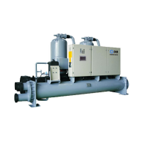
| Model | WCFX 30-30 |
| Category | Chiller |
| Language | English |