V
Valerie WilliamsOct 30, 2025
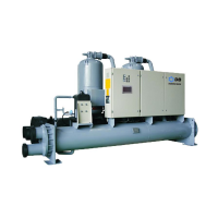
What to do if my Dunham-Bush WCFX Chiller unit will not start?
- AAustin JohnsonOct 30, 2025
If your Dunham-Bush Chiller won't start, there are several potential causes: * **Power Issues:** Verify that the main disconnect switch is on and the main line fuses are intact. * **Control Power:** Check the control transformer fusing. * **Compressor Circuit Breakers:** If the compressor circuit breakers are open, attempt to close them. If they trip again, inspect the compressor. * **Phase Control Relay:** If the phase control relay is open, check for power supply issues like low voltage or phase imbalance. Correct these issues and then press the reset button. * **Flow Switch:** Ensure pumps are running and check the flow switch. * **Compressor Switch:** Turn the compressor switch on and check the alarm status, correcting any problems. * **Microcomputer Shutdown:** Press t...