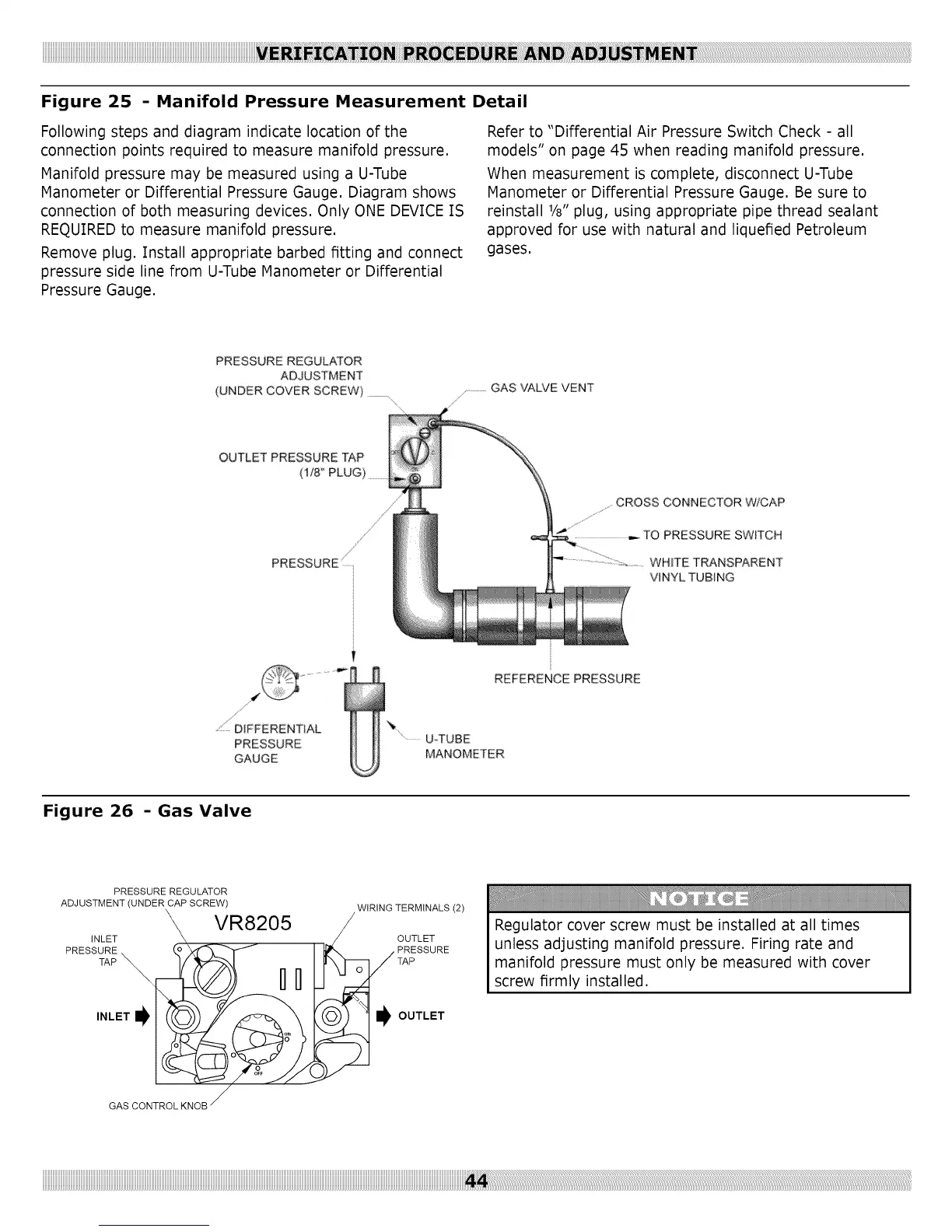
Figure 25 - Manifold Pressure Measurement Detail
Following steps and diagram indicate location of the
connection points required to measure manifold pressure.
Manifold pressure may be measured using a U-Tube
Manometer or Differential Pressure Gauge. Diagram shows
connection of both measuring devices. Only ONE DEVfCE [S
REC:)UIREDto measure manifold pressure.
Remove plug. Install appropriate barbed fitting and connect
pressure side line from U-Tube Manometer or Differential
Pressure Gauge.
Refer to "Differential Air Pressure Switch Check - all
models" on page 45 when reading manifold pressure.
When measurement is complete, disconnect U-Tube
Manometer or Differential Pressure Gauge. Be sure to
reinstall 1/8"plug, using appropriate pipe thread sealant
approved for use with natural and liquefied Petroleum
gases.
PRESSURE REGULATOR
ADJUSTMENT
(UNDER COVER SCREW) ..............
................GAS VALVE VENT
OUTLET PRESSURE TAP
(1/8_'PLUG)
/
PRESSURE
CROSS CONNECTOR W/CAP
PRESSURE SWITCH
WHITE TRANSPARENT
VINYL TUBING
DIFFERENTIAL
PRESSURE
GAUGE
REFERENCE PRESSURE
'....... U-TUBE
MANOMETER
Figure 26 - Gas Valve
PRESSURE REGULATOR
ADJUSTMENT (UNDER CAP SCREW) WIRING TERMINALS (2)
VR8205
INLET OUTLET
PRESSURE PRESSURE
TAP _
INLET_ _ OUTLET
Regulator cover screw must be installed at all times
unless adjusting manifold pressure. Firing rate and
manifold pressure must only be measured with cover
screw firmly installed.
GAS CONTROL KNOB