40
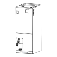
IMPORTANT: Do not operate the system without a lter in place.
• New lters are available from a local distributor or home supply retailer.
7.2 INDOOR COIL, DRAIN PAN, DRAIN LINE
Inspect the indoor coil, drain pan, and drain line once each year for cleanliness and
clean as necessary. Be sure to check the nned surface on the return side of the coil.
It may be necessary to remove the air-lter and use a mirror and ashlight to view the
return side of the coil.
NOTE: A proper lter is the best defense against a dirty coil. Regardless of the lter
choice, proper air ow and velocity also play a crucial role in how effective a lter will
be. Most lters will lose their effectiveness when face velocities exceed 300 - 400 feet
per minute. Excessive air velocity can allow particles to pass right through the media.
Additionally, loaded or restrictive lters may lose their shape in higher air velocity appli-
cations and allow unltered air to bypass the lter altogether around the sides.
IMPORTANT: Coil and Drainpan Cleaning Method
Clean the nned surface of the indoor coil by rinsing the coil from both sides with clean
warm water and/or with a vacuum with a soft brush attachment to remove accumulated
contaminants and lint. It is important not to allow the tool to damage or bend the ns.
Many chemical cleaners will attack the aluminum tubes which can cause refrigerant
leaks. Therefore, use only clean warm water for cleaning aluminum tube evaporator
coils. Do not use caustic household drain cleaners or bleach in the condensate pan or
near the indoor coil as they will damage the aluminum ns and tubes.
7.3 BLOWER MOTOR AND WHEEL
Inspect the blower motor and wheel for cleanliness. It should be several years before it
would become necessary to clean the blower motor and wheel.
• If it becomes necessary to remove the blower assembly from the unit, see instructions on
removal and replacement of motor, blower, and blower wheel in Sections 7.5-7.7 below.
• The blower motor and wheel may be cleaned by using a vacuum with a soft brush
attachment. Remove grease with a mild solvent such as hot water and detergent. Be
careful not to disturb the balance weights (clips) on the blower wheel blades. Do not
drop or bend wheel as balance will be affected.
7.4 MOTOR LUBRICATION
The blower motor sleeve bearings are pre-lubricated by the motor manufacturer and do
not have oiling ports. Motor should operate for an indenite period of time without addi-
tional lubrication.
7.5 BLOWER ASSEMBLY REMOVAL & REPLACEMENT
Removing the blower assembly is not normally required for normal service and mainte-
nance. Removal is necessary for replacement of defective parts such as motor, blower
wheel. After extended use, removal of the blower assembly may become necessary for
a thorough cleaning of the blower motor and wheel.
• Mark eld power supply wiring (for replacement) attached to terminal block or circuit
breaker(s) on blower assembly. Remove wiring from terminal block or circuit breaker(s).
• Mark low voltage control wiring (for replacement) where attached to unit control pig-
tails on right side of blower housing. Remove wire nuts attaching eld control wiring to
unit control pigtails.
• Remove 4 screws holding blower assembly to front channel of cabinet and pull blower
assembly from cabinet.
• To replace blower assembly, slide blower assembly into blower deck. Make sure
blower assembly engages lances in deck properly. If assembly hangs up, check to
make sure top and bottom are lined up in proper locations.
• Slide blower assembly to back of cabinet and make sure it is completely engaged.
• Replace 4 screws holding blower assembly to front channel of cabinet. Take care not
to strip screws.
• Replace low voltage control wiring with wire nuts and make sure wiring is per the wir-
ing diagram and all connections are tight and secure.
• Replace eld power wiring to terminal block or circuit breaker(s) on control area of
blower assembly. Make sure wires are connected per the wiring diagram. Tighten
WARNING
If removal of the blower assembly is required, all disconnect switches supply-
ing power to the equipment must be de-energized and locked (if not in sight of
unit) so the eld power wires can be safely removed from the blower assembly.
Failure to do so can cause electrical shock resulting in personal injury or death.
!
supply power wiring securely to terminals lugs.
 Loading...