To prevent serious injury from accidental operation:
turn the power switch off and unplug the welder
before set up.
WARNING!
8
Wire spool installation/Wire setup
1. Turn the Power switch OFF and unplug the welder
before proceeding.
2. Pull up the door latch, then open the door.
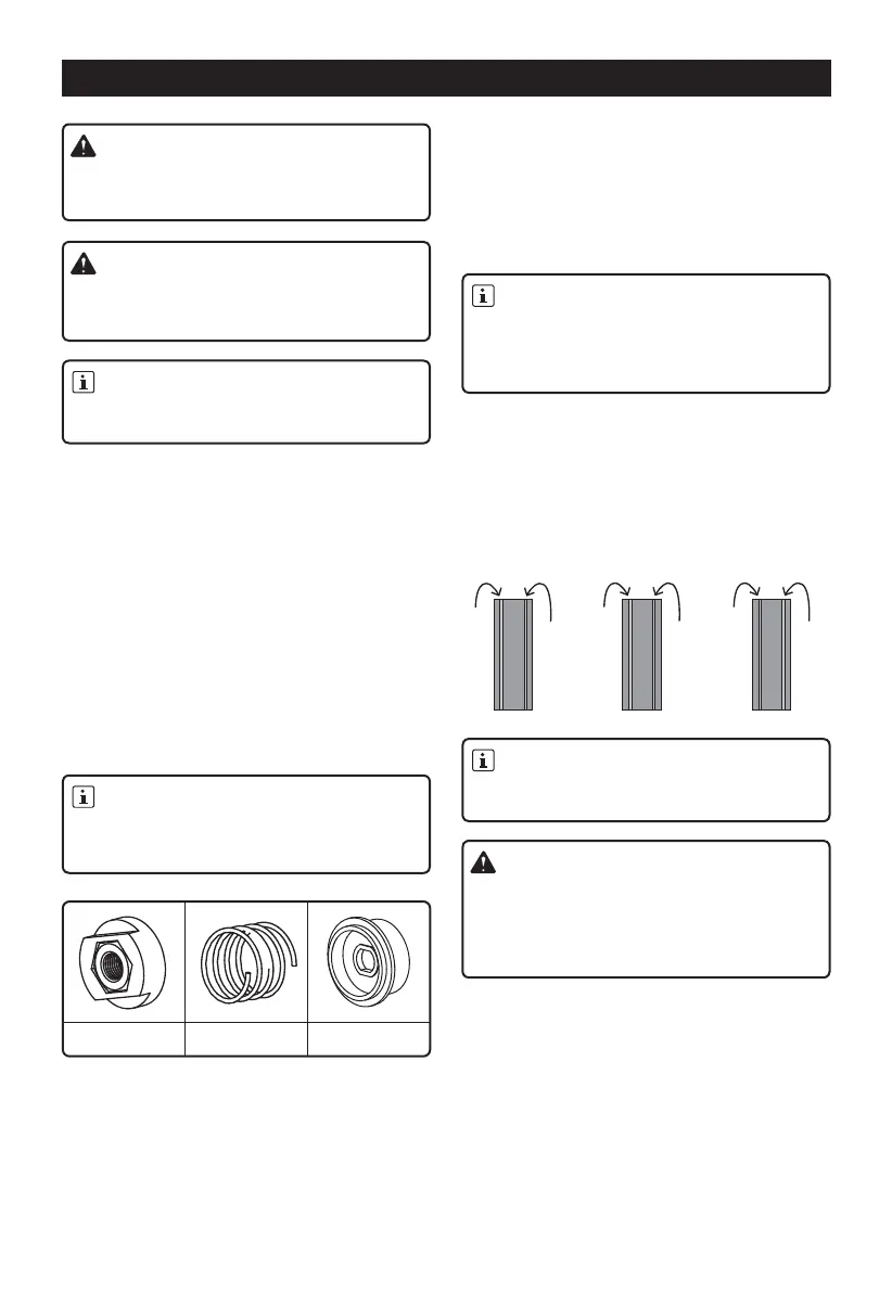
3. Wire Spool Installation. Remove the nut, spring and
spacer. If replacing a spool, remove the old spool
and all remaining wire from the liners.
4. Place the new wire spool over the spool spindle
and against the spool brake pad. To prevent wire
feed problems, set the spool so that it will unwind
clockwise.
5. Secure the spool in place with the Spacer, Spring
and Nut. (The spacer can be used both side to
adjust the tightness for 2 pounds spool and 10~12
pounds spool.)
Feed roller instructions:
Check that the feed roller is correct for the type of
wire being used(solid core or flux-cored) and that it is
turned to properly match the wire size marked on the
wire spool. (2pcs V-rollers for solid wire and 1pc
K-roller for flux-cored wire)
6. Dcen direct current electrode negative wire setup
for flux-cored (gasless) welding: connect the
polarity jumper to the negative terminal on the front
of the welder. connect the ground cable to the
positive terminal on the front of the welder.
7. Dcep direct current electrode positive wire setup
for solid core (gas shielded) welding:
Securely hold onto the end of the welding wire
and keep tension on it during the following steps.
If this is not done, the welding wire will unravel
and unspool which can cause tangling and
feeding problems.
IMPORTANT!
Read the entire important safety information
section at the very beginning of this manual
including all text under subheadings therein
before set up or use of this item.
MIG/FLUX-CORED WIRE WELDING
Remove the protective foam and cardboard from
the welder before set up.
NOTE:
If wire spool can spin freely, nut too loose. This
will cause the welding wire to unravel and unspool
which can cause tangling and feeding problems.
NOTE:
When using C100 shielding gas, connect a CGA
580/320 adapter (not included) to the inlet connection
of the Regulator and wrench tighten. Thread the
adapter onto the gas cylinder and wrench tighten.
NOTE:
To prevent damage, don’t overtighten the
tensioner.
NOTE:
Nut Spring Spacer
a. Connect the polarity jumper to the positive terminal
on the front of the welder. connect the ground
cable to the negative terminal on the front of the
welder.
b. Determine which type of shielding gas would be
appropriate for the welding you will do. Refer to the
Settings Chart on the inside of the Welder door.
8. Cut off all bent and crimped wire. The cut end must
have no burrs or sharp edges; cut again if needed.
9. Keep tension on the wire and guide at least 12
inches of wire into the Wire Inlet Liner and Feed
Guide.
10. Make sure the welding wire is resting in the groove
of the Feed Roller, then push the wire Idler Arm
down, and swing the Feed Tensioner up to latch it
across the tip of the arm.
11. After the wire is held by the Tensioner, you may
release it.
0.025
V-groove
0.030
V-groove
V-groove
Solid Wire Wire
V-Groove
Solid
V-Groove
0.030
V-groove
0.035
K-groove
Wire
Flux
K-Groove
0.030
K-groove
0.035
 Loading...