305 mm
max. / máx.
1
/
4" / 6,5 mm
12"
Shut-off valve
Llave de paso
ܸхً
4
7
/
8"
125 mm
8
7
/
8"
225 mm
1 2 3 4
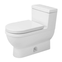
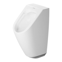
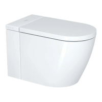
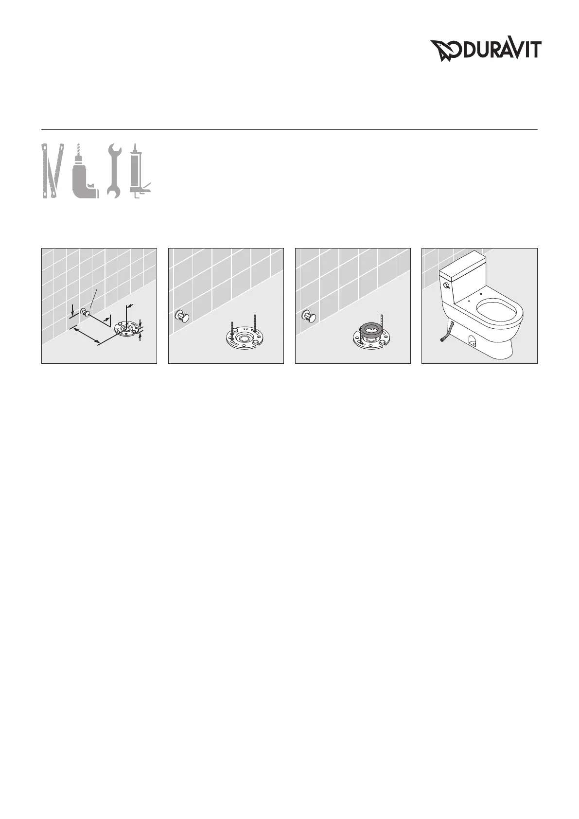
INSTALLATION OF THE TOILET
Standard US installation dimen-
sions are indicated above.
The flange must not exceed
1
/4"/ 6.5
mm above the finished floor.
INSTALACIÓN DEL INODORO
Las dimensiones estándar de
in-stalación para los Estados Uni-
dos están indicadas arriba.
La brida no debe sobresalir más de
1
/4” / 6.5 mm sobre el suelo acaba-
do.
ቝѓఝτሔ"
њሠૌ൛ቝѓఝτሔԋձഏ
൜è
ٌম၉҉Әݝຢӵޱ֬׀ၢ
ഏ
1
/4"/6.5mm.
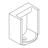
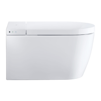
If the floor flange has not been se-
cured to the building structure affix
it accordingly using screws and fas-
teners.
Install the toilet bolts at the 3 and
9 o‘clock position, equally spaced
from the finish wall.
Si la brida del inodoro no se ha ase-
gurado a la estructura de la edifi-
cación, fíjela debidamente usando
tornillos y sujetadores.
Coloque los pernos del inodoro en
las posiciones correspondientes a
las 3 y 9 horas, con igual separación
a la pared acabada.
ݛ׀ٌমેႼᄤ٣ࢀሄ൏ܬ
ƗᄼႯઋරދࡸࢃఊཔ႒ܬ
èᄤ3ᇙދ9ᇙ֬໑ᇉτሔቝ
ѓఝઋඤƗൗఊთຢӵు֬ঢ়
པְè
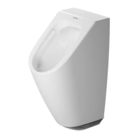
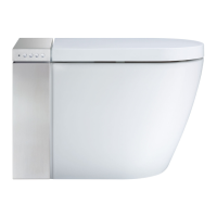
Place the new wax-ring around the
outlet hole of the floor flange.
Coloque la nueva junta alrededor
del agujero de desagüe de la brida
en el suelo.
ᄤ׀ٌমᇢຽ٩ᇉড૨چ
ߓè
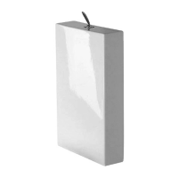
Connect the flexible water supply
line with the tank.
Conecte el tubo flexible de ali-
mentación de agua a la cisterna.
ࢃ܉ඪܼთඪམৼࢫè
MAL_53758/14.02.2 5