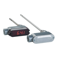
Do you have a question about the Dwyer Instruments 641 series and is the answer not in the manual?
Defines the type of air and compatible gases the transmitter can be used with.
Specifies the accuracy of the process gas measurement at different temperature ranges.
Indicates the time it takes for the output to reach 95% of the final value.
Defines the operating temperature ranges for both process and ambient conditions.
Specifies the maximum allowable pressure for the transmitter.
Defines the acceptable humidity conditions for operation (non-condensing).
Details the voltage and current requirements for powering the transmitter.
Describes the isolated 4-20 mA output signal and connection types.
Specifies the selectable output filter for smoothing readings in turbulent flow.
Indicates the maximum allowable loop resistance for proper operation.
States the maximum current the transmitter will draw.
Details the type of screw terminals used for electrical connections.
Specifies the 1/2" male NPT for process connections.
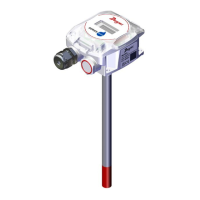
States that the unit is not position sensitive but the probe must align with airflow.
Provides the weight of the transmitter.
Lists CE approval standards used for the product.
Details the specifications for the optional 4-1/2 digit LED display.
Guidance on selecting a suitable location for mounting the enclosure based on temperature.
Notes that the transmitter is not position sensitive but the probe must align with airflow.
Instructions for mounting the transmitter using integral 1/2" NPT or compression fittings.
Recommendations for using the transmitter with clean, dry air and avoiding dust accumulation.
Explains the flexible connection options for power and loop receivers.
Describes the isolated current loop output and cautions against external supplies.
Details power supply options (AC or DC) and recommended voltages.
Provides guidelines for wire selection and length to ensure satisfactory operation.
Instructions for selecting one of eight ranges in FPM or MPS.
Guidance on adjusting the output filter time constant for damping.
Process for adjusting the span to correct for altitude or static pressure changes.
Procedure for calibrating the 4 mA set-point using a milliammeter.
Procedure for calibrating the 20 mA set-point using a milliammeter.
Steps to restore factory default settings for range, 4 mA, and 20 mA.
Instructions for cleaning the sensor to remove dust accumulation.
Information on returning the unit to Dwyer Instruments for factory calibration.
| Model | 641 Series |
|---|---|
| Category | Transmitter |
| Manufacturer | Dwyer Instruments |
| Output Signal | 4-20 mA |
| Agency Approvals | CE |
| Relative Humidity | 0-95% non-condensing |