Do you have a question about the Dwyer Instruments Magnesense Pro MSX Series and is the answer not in the manual?
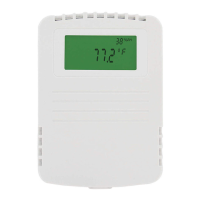
Mount transmitter on a vertical surface using specified screws.
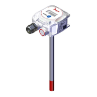
Mount transmitter in duct away from obstructions, using probe and flange.
Wiring instructions for the 4-20 mA current output using a 2-wire connection.
Wiring instructions for 0-5 V or 0-10 V voltage output using 3-wire connection.
Configure pressure or velocity/flow units using DIP switches 1 and 2.
Select between pressure, velocity, or flow mode using DIP switch 3.
Set voltage output range to 0-10 V or 0-5 V using DIP switch 4.
Configure unidirectional or bidirectional measurement using DIP switch 5.
Set response time to instantaneous or 3 seconds using DIP switch 6.
Select pressure or velocity/flow ranges using DIP switches 7 and 8.
Set the zero point by applying zero pressure and pressing the zero button.
Set the span by applying maximum pressure and pressing the span button.
Explains various error codes displayed on the LCD screen.
Describes how to set or disable the PIN code for menu access.
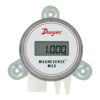
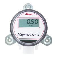
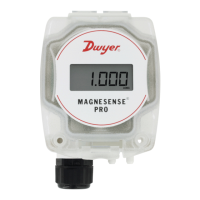
The Series MSX Pro Magnesense® Differential Pressure Transmitter is a professional-grade device designed for precise differential pressure measurement in critical building performance applications. It builds upon the versatility of the original Series MS2 Magnesense® II transmitter, offering enhanced stability and a streamlined ordering process to reduce setup time. This transmitter is capable of measuring pressure in Pa, mm w.c., and in w.c. units, with all pressure ranges configurable for either unidirectional or bidirectional modes, providing a total of 32 distinct ranges.
A key feature of the MSX Pro is its flexible output capabilities. It can provide a linear pressure output or a linear velocity output, which includes square root extraction from the transmitter. This allows for the calculation of flow, expanding its utility in various HVAC and industrial settings. The device also supports dual voltage and milliamp output signals, enabling comprehensive control and equipment output signal verification.
For installation, the MSX Pro can be surface-mounted or duct-mounted, depending on the model. When surface mounting, it should be placed on a vertical surface with connections facing downwards to prevent moisture ingress. The mounting flange is secured with #8 x 1/2" pan head sheet metal screws, ensuring a secure fit without overtightening. For duct mounting, a .562" (12.70 mm) diameter hole is drilled into the duct, and the duct probe is screwed into the back of the housing before inserting it into the duct. Mounting holes are then marked using the flange as a template, drilled, and secured with #8 x 1/2" pan head sheet metal screws. An included cap is placed on the exterior positive pressure port. It is crucial to mount the transmitter away from fans, corners, heating and cooling coils, and other equipment that could interfere with pressure measurements. The universal model can also function as a standard wall mount without the duct probe, by plugging the port on the backside with the included plug.
The electrical connections for the MSX Pro are versatile, supporting either a 2-wire 4-20 mA Current Output or a 3-wire 0-5 V/0-10 V Voltage Output. It also offers simultaneous current and voltage output. Power and signals are interconnected via a removable European-style four-conductor terminal block, or an optional toolless terminal block. For 2-wire 4-20 mA current output, connections are made to the VDC and COM terminals. Shielded 2-wire cable is recommended for control loop wiring, with the shield grounded at the power supply end. The transmitter is designed to prevent damage even if the polarity of the transmitter or receiver is inadvertently reversed, though it will not function properly in such a case.
For 3-wire 0-10 V and 0-5 V voltage output, the selection of DC or AC power supply is made via the terminal block. The terminal block is removable, and terminals are labeled on the circuit board. Positive polarity is indicated by VOUT. Similar to the current output, inadvertent polarity reversal will not damage the unit but will prevent proper function. The minimum receiver load for voltage outputs is 1 kΩ.
When using simultaneous current and voltage output, the VDC terminal and a DC power supply must be used. The voltage output and power supply require separate wire leads joined only at terminal 2 of the transmitter to avoid additional errors. Shielded 4-wire cable is recommended, with the shield grounded at the power supply end.
The device features digital push-button adjustments for zero and span. If equipped, an LCD display must be removed before wiring and reinstalled afterward. DIP switches are used to configure various settings, including unit of measure, velocity/flow unit selection, voltage output range, unidirectional/bidirectional operation, response time, and maximum pressure range. These switches are factory-set based on the order configuration but can be changed with a small screwdriver or pen. It is advisable to shut down control systems when changing DIP switches to prevent erratic behavior.
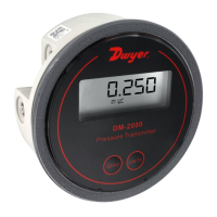
The optional 4-digit LCD display provides real-time pressure readings and engineering units. The LCD is 180° rotatable, ensuring readability regardless of mounting orientation. It also displays error messages such as "OVER" (over range), "UNDR" (under range), "FAIL" (span button pressed out of range), and various "ER" codes indicating sensor or memory issues.
The MSX Pro includes a program menu for configuration. By default, a PIN code is not required to access the menus. However, security can be enabled by setting a PIN between 0001 and 9999. This involves pressing and holding the Zero and Span buttons until "PIN" is displayed, then entering the desired PIN using the Zero button to increment digits and the Span button to select the next digit. A PIN of 0000 disables the security feature.
Calibration features include a security feature that must be unlocked before calibration. The "Security Menu-Menu Access Security" section describes how to delay the zero or span calibration buttons until a specific time, preventing accidental changes. Zero calibration involves applying zero pressure and holding the Zero button for 3 seconds. Span calibration involves applying a positive pressure and holding the Span button for 3 seconds. The transmitter automatically adjusts the maximum analog output at the set pressure.
For maintenance, the Series MSX Pro requires no routine maintenance after final installation. It is not field serviceable and should be returned to the manufacturer for repair if needed, as attempted field repair may void the warranty. The device is designed to be environmentally responsible, with a symbol indicating that waste electrical products should not be disposed of with household waste but recycled where facilities exist.
| Model | MSX Series |
|---|---|
| Category | Transmitter |
| Manufacturer | Dwyer Instruments |
| Product Line | Magnesense Pro |
| Storage Temperature | -40 to 85°C (-40 to 185°F) |
| Enclosure Rating | NEMA 4X (IP66) |
| Agency Approvals | CE, RoHS |
| Power Supply | 12 to 30 VDC |
| Accuracy | ±0.5% FS |
| Wetted Materials | 316 Stainless Steel |
| Output | 4-20 mA, 0-10 VDC, RS-485 Modbus |