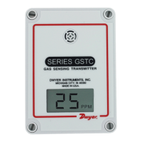
Series GSTA Carbon Monoxide/Nitrogen Dioxide Gas Transmitters
Specications - Installation and Operating Instructions
Bulletin AQ-GSTA
The Series GSTA Carbon Monoxide/Nitrogen Dioxide Transmitters monitor the gas
concentration in underground parking garages and loading docks. Carbon monoxide
is commonly used to measure the exhaust of gasoline engines, while nitrogen dioxide
is used for diesel engines. Field selectable current and voltage outputs allow the
transmitter to be used with almost any building management controller. For carbon
monoxide units, the user can adjust the output range to be 0 to 50 ppm up to 0 to 599
ppm. Nitrogen dioxide units come with a standard 0 to 10 ppm range. The output can
be inverted to read 20 to 4 mA or 10 (5) to 0 VDC using internal dip switches.
To maximize the accuracy of the Series GSTA, the sensor can be eld-calibrated using
the A-449 remote LCD display. When the sensor reaches the end of its life, the display
will indicate that the sensor needs to be replaced.
INSTALLATION
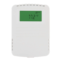
• The transmitter should be mounted at normal breathing height, approximately 5 to 6
ft above the oor.
• The unit may be mounted in the horizontal or vertical position. It should be mounted
in an area that is shielded from direct contact with the elements or direct sunlight.
• Mount in an area that will prevent the sensor from having any direct contact with
water.
• The unit should be placed in an area that will give an average of the air quality. Do
not place the unit so it will receive direct engine exhaust. Prolonged exposure to
direct engine exhaust may damage the sensor.
MOUNTING
1. Remove the cover plugs from the face of the unit and the top cover.
2. Disconnect the display cable from the USB connector on the main circuit board (if
present).
3. Remove the desired conduit tting knock out and install conduit tting (not
provided).
4. Position the transmitter where it is to be mounted and mark the mounting holes in
each corner of the housing.
5. Drill or punch out marked locations.
6. Place the transmitter box over mounting holes on wall and align. Install wall mount
screws (not provided) in mounting holes.
7. Proceed with wiring according to Figures 1 and 2.
8. Set DIP SWITCH and IOUT/VOUT SWITCH as desired. Refer to Figure 3.
9. Reconnect the LCD cable to the USB port on the main circuit board (if present).
10. Replace cover and cover plugs on the face of the unit.
SPECIFICATIONS
Sensor: Field replaceable electrochemical, 4 years typical lifespan.
Range: CO: selectable 0 to 50 ppm up to 0 to 500 ppm ; NO
2: 10 ppm.
Output Drift: <5% per year in air.
Coverage Area: 5000 to 7500 sq ft typical.
Accuracy: CO: ±2% FS., NO
2: ±3% FS., at the time of calibration.
Resolution: CO: 1 ppm; NO
2: 0.1 ppm.
Temperature Range: -4 to 122°F (-20 to 50°C).
Storage Temperature: For best sensor life, 32 to 68°F (0 to 20°C).
Humidity Limits: 15 to 90% RH constant; 0 to 99% RH intermittent.
Response Time: <45 seconds to 90% CO, <25 to 90% NO
2.
Span and Zero Adjustment: Via pushbutton, using optional A-449 display.
Housing: UV resistant glass lled polycarbonate.
Output: Switch selectable 4 to 20 mA (loop powered), 0 to 5 V @ 5 mA, or 0 to 10
V @ 5 mA; Switch selectable 0 to 5 V / 1 to 5 V and 0 to 10 V / 2 to 10 V; Switch
selectable normal or reverse output.
Power Supply: Current output: 10 to 35 VDC; Voltage output: 15 to 35 VDC or 15
to 29 VAC.
Electrical Connection: Removable terminal block, knock outs for conduit tting.
Calibration: Via pushbuttons using A-449 auxiliary display. Span gas concentration
is eld selectable.
Weight: 1 lb (.45 kg).
Agency Approval: CE.
Duct mountWall mount
3-45/64
[94.06]
3-1/8
[107.95]
2-15/64
[56.75]
4-17/32
[115.09]
5-7/64
[129.78]
3-59/64
[100]
2-15/64
[57]
2-55/64
[73]
[85]
The electrochemical sensors should be stored in an environment
with a minimum humidity level of 20% RH. If the sensor dries out,
replacements will not be covered under warranty, but they can be revived by allowing
them to stabilize in an environment above 40% RH for 10 days. Once revived, they
need to be recalibrated before use.
These are general guidelines. Local laws or ordinances will take
precedence.
NOTICE
NOTICE
Disconnect power supply before installation to prevent electrical
shock and equipment damage. Make sure all connections are in
accordance with the job wiring diagram and in accordance with national and local
electrical codes. Use copper conductors only.
WARNING
Use electrostatic discharge precautions (e.g., use of wrist straps)
during installation and wiring to prevent equipment damage.
Avoid locations where severe shock or vibration, excessive
moisture or corrosive fumes are present.
Do not exceed ratings of this device, permanent damage not
covered by warranty may result. The 4 to 20 mA models are not
designed for AC voltage operation.
CAUTION
CAUTION
CAUTION
DWYER INSTRUMENTS, INC.
P.O. BOX 373 • MICHIGAN CITY, INDIANA 46360, U.S.A.
Phone: 219/879-8000
Fax: 219/872-9057
www.dwyer-inst.com
e-mail: info@dwyermail.com