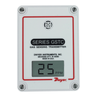
DUCT MOUNTING
Duct mounting kit includes an air ow pitot tube, air lter with barbed connections, two
short pieces of tubing and one long piece of tubing.
1. Mount the pitot tube into the duct observing the ow direction marked on the pitot
tube.
2. Attach the two short pieces of tubing to the barbed connections on each side of the
air lter.
3. Attach the remaining side of one of the short pieces of tubing to the barbed
connection on the transmitter.
4. Attach the remaining side of the other short piece of tubing to the high port on the
pitot tube.
5. Attach the long piece of tubing to the open barbed connection on the transmitter.
6. Attach the other end of the long tubing to the low port on the pitot tube.
WIRING
Use maximum 18 AWG wire for wiring terminals. Refer to Figure 1 or Figure 2 for
wiring information. The terminal block is removable for ease of installation.
Wiring for 4 to 20 mA Output
4 to 20 mA output units may be powered by 10 to 35 VDC.
Wiring for 0 to 5 or 0 to 10 V output
The 0 to 5 or 0 to 10 V units may be powered by 15 to 35 VDC or 15 to 29 VAC. Note
polarity when using DC power. The maximum load is 5 mA
(1 K ohms for 0 to 5 V or 2 K ohms for 0 to 10 V).
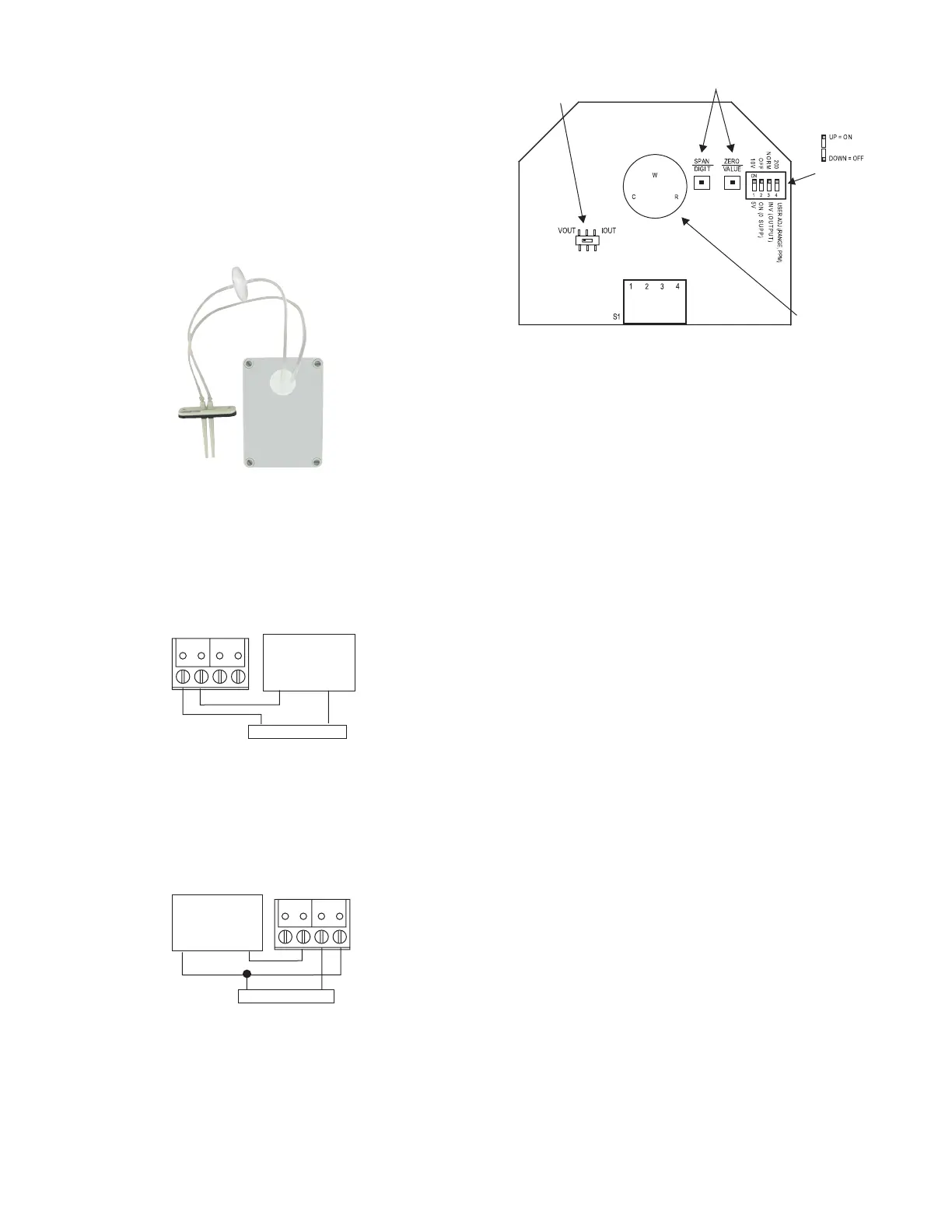
SWITCH LOCATIONS
Setting the Current/Voltage Select Switch
To access the current/voltage select switch, remove the cover of the unit. The current/
voltage select switch is located on the circuit board as shown in Figure 3. Set the
switch to ˝IOUT˝ for current, ˝VOUT˝ for voltage.
DIP SWITCH Settings
To access the DIP SWITCH, remove the cover of the unit. The DIP SWITCH is located
on the circuit board as shown in Figure 3.
ALL DIP SWITCHES ARE FACTORY SET TO “ON”.
5 V / 10 V Output Select (Applies only to Voltage Output)
DIP SWITCH #1 OFF: Output = 0 to 5 V
DIP SWITCH #1 ON: Output = 0 to 10 V
Zero Suppression (Applies only to Voltage Output)
DIP SWITCH #2 OFF: Output range = 1 to 5 V or 2 to 10 V, depending on output range
DIP SWITCH #2 ON: Output range = 0 to 5 V or 0 to 10 V, depending on output range
Output Normal or Invert
DIP SWITCH # 3 OFF: Output is inverted
DIP SWITCH # 3 ON: Output is normal
Menu Function (CO Model only)
DIP SWITCH #4 OFF: User ADJ (Output Range)
DIP SWITCH #4 ON: Sensor calibration/range = 200 ppm
1
2
3
4
-
+
-
+
POWER
SUPPLY
1
2
3
4
-
+
-
+
POWER
SUPPLY
SELECT SWITCH
DIP SWITC
Figure 3
Figure 1
Figure 2
 Loading...