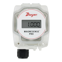
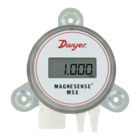
Series MSX Magnesense
®
Differential Pressure T
ransmitter
Specications - Installation and Operating Instructions
Bulletin P-MSX-A
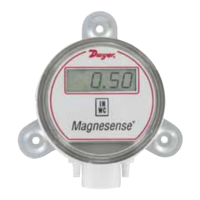
The Series MSX Magnesense
®
Differential Pressure
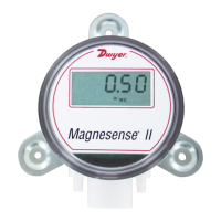
Transmitter combines the
stability and versatility of the original Series MS2 Magnesense
®
II
transmitter for use
in building control applications. The MSX simplies the ordering process to deliver the
desired conguration, which reduces product setup time. Pressure ranges are available
in Pa, mm w.c., and in w.c. All pressure ranges can be congured in unidirectional or
bidirectional modes, providing a total of 32 ranges. The MSX transmitter can provide
a linear pressure output or a linear velocity output with the square root extraction from
the transmitter. Additional parameters have been included to expand the square root
capability to calculate ow. Dual voltage and milliamp output signals can be used to
provide both control and equipment output signal verication.
INSTALLATION
Surface Mounting:
Mount the transmitter on a vertical surface. The pressure sensor measurement
is unaffected by orientation, but it is recommended the unit be mounted with the
connections facing down to prevent moisture from entering either the pressure ports
or the electrical cable entry. Attach the mounting ange to a at surface using #8 x 1/2˝
pan head sheet metal screws. Do not over tighten.
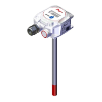
Duct Mounting (Universal model required):
Mount the transmitter away from fans, corners, heating and cooling coils and other
equipment that will affect the measurement of the pressure.
1. To mount the transmitter, drill a .562˝ (12.70 mm) diameter hole into the duct.
2. Screw duct probe into back of housing. Insert transmitter probe into the duct.
3. Mark location of mounting holes on duct using mounting ange as template. Drill
holes.
4. Attach mounting ange to duct with #8 x 1/2˝ pan head sheet metal screws. Do
not over tighten screws.
5. Place the included cap on the exterior positive pressure port.
The Universal model can also be used as a standard wall mount transmitter. In this
mode,
do not use the duct probe and plug the port on the backside of the transmitter
with the included plug.
SPECIFICA
TIONS
Service: Air and non-combustible,
compatible gases.
Wetted Materials: Consult factory.
Accuracy: ±1% FSO.
Stability: ±1% FSO/year.
Temperature Limits: -4 to 158°F (-20
to 70°C).
Pressure Limits: Ranges 0 and 1: 3.6
psi max operation, 6 psi burst; Ranges 2
and 3: 6 psi max operation, 6 psi burst.
Power Requirements: 10-36 VDC
(2-wire), 17-36 VDC or isolated 21.6-33
VAC (3-wire).
Output Signals: 4-20 mA (2-wire); 0-10
V or 0-5 V selectable (3-wire).
Response Time: Instantaneous (default)
or 3 s (selectable).
Zero and Span Adjustments: Digital
push-button.
Loop Resistance: Current output:
0-1250 Ω max; Voltage output: min. load
resistance 1 k Ω.
Current Consumption: 21 mA max
continuous.
Electrical Connections: 4-wire
removable European style terminal block
for 16 to 26 AWG.
Electrical Entry: 1/2˝ NPS thread.
Display (optional): 4 digit LCD.
Process Connections: 1/8˝, 3/16˝, 1/4˝,
5 mm, and 6 mm ID exible tubing.
Enclosure Rating: NEMA 4X (IP66); UL
2043 (Plenum); UL94 V-0.
Mounting Orientation: Pressure sensor
measurement unaffected by orientation.
Weight: 8.0 oz (230 g).
Agency Approvals: CE.
1-31/32
[49.89]
3-9/64
[79.96]
1/2 NPSM
1-1/16 [26.92
]
33/64
[13.08]
1-3/16 [30.02]
1
1/32 [8.56]
2-3/32
[53.34]
2-9/32
[57.79]
2-9/16
[64.96]
[3] 3/16 [4.57] HOLES
EQUALLY SP
ACED ON A
4-7/64 [104.53] BC
7-31/64 [190.12]
3/8 [9.53]
1-29/32
[48.36]
3-9/64
[79.96]
1/2 NPSM
1-1/16 [26.92
]
33/64 [13.08
]
1-3/16
[30.02]
1
1/32
[8.56]
2-3/32
[53.34]
2-9/32
[57.79]
1-43/64
[42.50]
13/32
[10.29]
3-5/8
[92.08]
3-15/32
[88.19]
W
all mount bracket
Duct mount bracket
DIN mount bracket
OPTIONS
Range in w
.c. Pa low Pa high mm w.c.
Range 0 0.1
0.15
0.25
0.5*
25
30
40
50
60
75
100
125*
2.5
5
10
12*
Range 1 0.1
0.25
0.5
1*
25
40
50
60
100
150
160
250*
2.5
5
10
25*
Range 2 1
2
3
5*
250
300
400
500
600
750
1000
1250*
25
50
100
125*
Range 3 10
15
25
28*
1000
1500
2000
2500
3000
4000
5000
7000*
250
350
500
700*
*Indicated values are the positive full scale output values per range.
DWYER INSTRUMENTS, INC.
7Jwyer.
1
Polígono Industrial O Rebullón s/n. 36416 - Mos - España - rodavigo@rodavigo.com
https://rodavigo.net/
Polígono Industrial O Rebullón s/n. 36416 - Mos - España - rodavigo@rodavigo.com
Servicio de Att. al Cliente
+34 986 288118