ELECTRICAL
The MSX transmitter utilizes a 2-wire 4-20 mA Current Output, or a 3-wire 0-5 V
/ 0-10 V Voltage Output. It is also capable of Simultaneous Current and Voltage
Output. The power and signals interconnect via a removable European-style four
conductor terminal block.
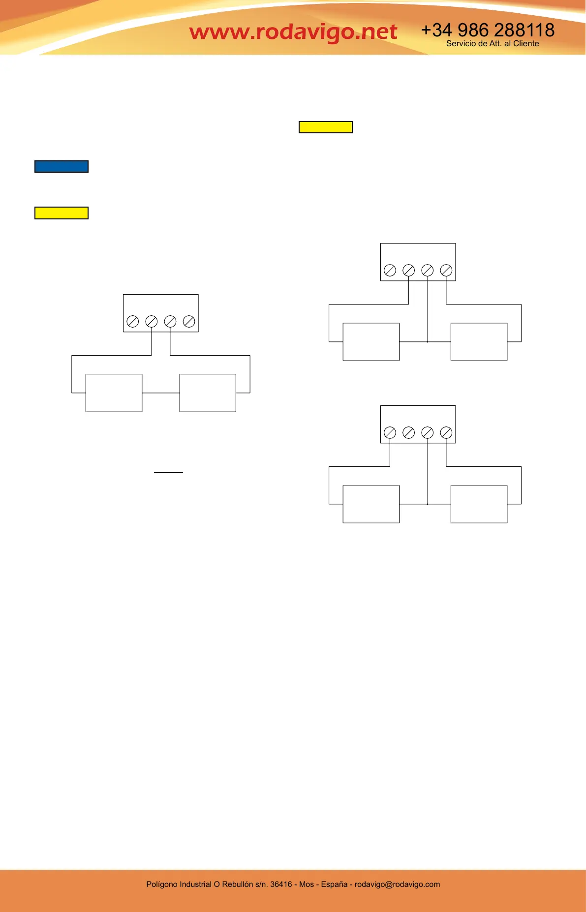
2-Wire 4-20 mA Current Output
The connections to the transmitter are made through terminals VDC and COM on
the terminal block as shown in Figure 1. The terminal block is removable and each
of the terminals are labeled next to the terminal block on the circuit board. Polarity is
indicated by VDC and COM. See Figure 1.
The maximum receiver load resistance (R
L) for a given power supply voltage (Vps) is
dened by the formula:
Shielded 2-wire cable is recommended for control loop wiring. Ground the shield at the
power supply end only.
The receiver may be connected to either the negative or positive side of the loop,
whichever is most convenient. Should polarity of the transmitter or receiver be
inadvertently reversed, the loop will not function properly but no damage will be done
to the transmitter.
The maximum length of connecting wire between the transmitter and the receiver is
a function of wire size and receiver resistance. That portion of the total current loop
resistance represented by the resistance of the connecting wires themselves should
not exceed 10% of the receiver resistance. For extremely long runs (over 1,000 feet), it
is desirable to select receivers with lower resistances in order to keep the size and cost
of the connecting leads as low as possible. In installations where the connecting run
is no more than 100 feet, you can use a connecting lead wire as small as No. 22 ga.
3-Wire 0-10 V and 0-5 V Voltage Output
The terminal block is removable and each of the terminals are labeled next to the
terminal block on the circuit board. Positive polarity is indicated by VOUT. AC/DC
selection is made via the terminal block. If the polarity of the transmitter is inadvertently
reversed, the unit will not function properly, but no damage will be done to the
transmitter.
Selection of using a DC or AC power supply is made via the terminal block.
See Figure 2 for DC Wiring.
See Figure 3 for AC Wiring.
The minimum receiver load is 1 kΩ. The resistance due to the wire should be low
compared to the receiver load resistance. While the voltage at the terminal block
remains unchanged with a 10 mA current ow, resistive losses in the wiring do cause
errors in the voltage delivered to the receiver. For a 1% accurate gage, the resistance
of the wires should be less than 0.1% of the value of the receiver load resistance. This
will keep the error caused by the current ow below 0.1%.
The output across VOUT and COM will be either 0-5 V, 0-10 V depending on the DIP
switch setting. See DIP Switch Settings Section for more information.
DC POWER
SUPPLY
10-36 VDC
VAC
VDC
COM
VOUT
CURRENT
RECEIVER
+
-
+ -
DC POWER
SUPPLY
17-36 VDC
VOLTAGE
RECEIVER
+
-
VAC
VDC
COM
VOUT
+
-
AC POWER
SUPPLY
21.6-33 VAC
VOLTAGE
RECEIVER
+
-
VAC
VDC
COM
VOUT
DO NOT EXCEED SPECIFIED SUPPLY VOLTAGE RATINGS.
PERMANENT DAMAGE NOT COVERED BY WARRANTY WILL
RESULT. SIMULTANEOUS OUTPUTS ARE NOT DESIGNED FOR AC VOLTAGE
OPERATION.
CAUTION
DO NOT EXCEED SPECIFIED SUPPLY VOLTAGE RATINGS.
PERMANENT DAMAGE NOT COVERED BY WARRANTY WILL
RESULT.
CAUTION
Figure 1
Figure 2: DC wiring
Figure 3: AC wiring
R
L =
V
ps - 10.0
20 mA DC
If equipped, the LCD must be removed before wiring. Pull the LCD
directly away from the product to remove. Reinstall the LCD after
wiring is completed.
NOTICE
-
0
0 0
-
~
Polígono Industrial O Rebullón s/n. 36416 - Mos - España - rodavigo@rodavigo.com
https://rodavigo.net/
Polígono Industrial O Rebullón s/n. 36416 - Mos - España - rodavigo@rodavigo.com
Servicio de Att. al Cliente
+34 986 288118
 Loading...